background image

D

IGITAL  

C

ONTROL  

I

NCORPORATED

Supplement B for DigiTrak® Falcon F5®

5

Optimizing with Sub-k

Rebar

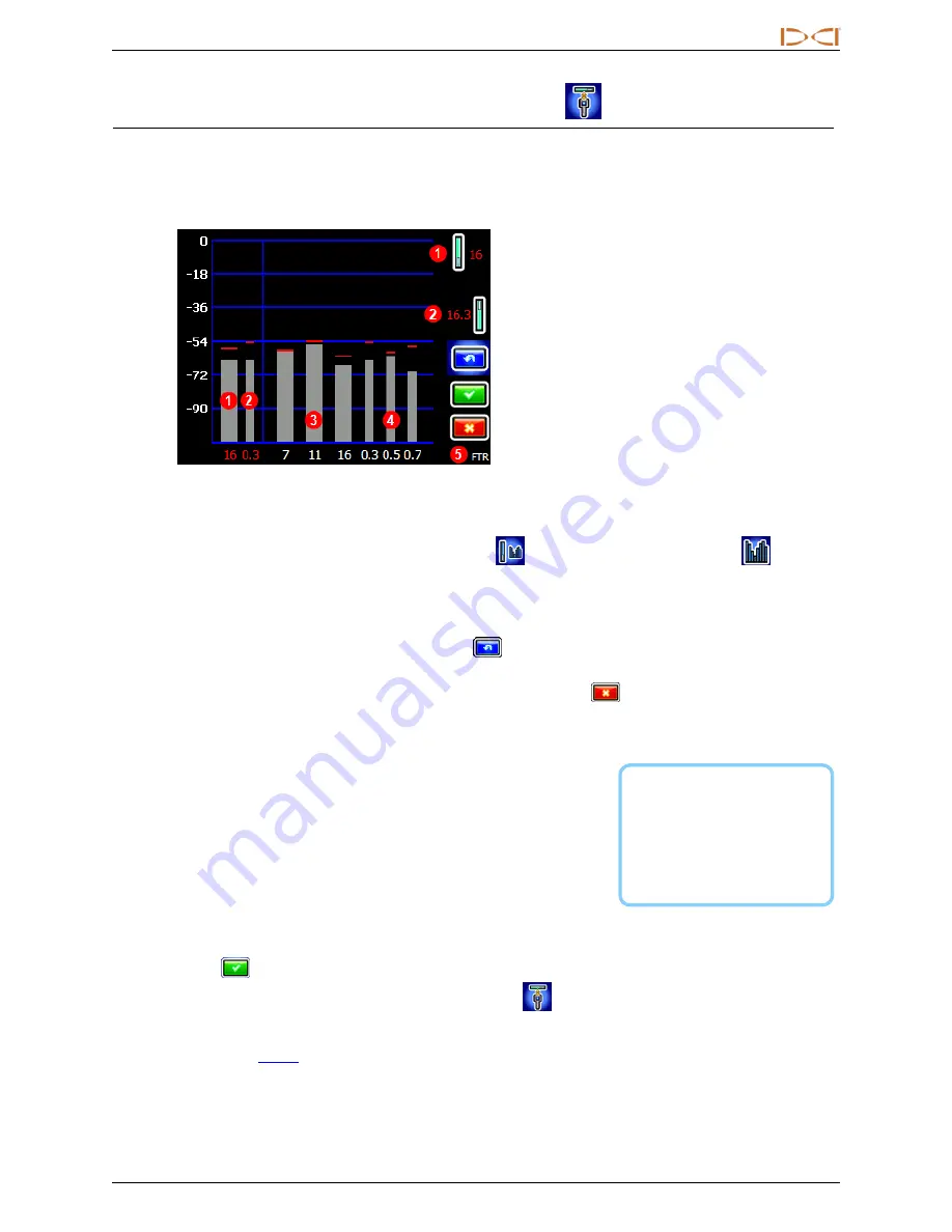
The frequency optimizer (FO) has a slightly different look when you use a Sub-k™ Rebar transmitter. In
addition to the currently optimized FO bars at the left, the remaining bars show the active interference (noise)
in just six low-frequency bands.

1.

Up mode band (one)

2.

Down mode bands (two)

3.

Interference in data bands 7–16

4.

Interference in depth bands 0.3–0.7

5.

Current transmitter

FO Screen for Rebar Transmitter

Here's how to optimize with a Sub-k transmitter:

1. From the Main menu, select

Transmitter Selection

, then

Frequency Optimization

.

2. With the transmitter off, walk the bore while observing interference levels in the two currently

optimized bands (left side of screen). Interference will be greatest where two bars are highest, and
recorded by the red Maximum marks.

3. At the point of greatest interference, select

Scan

to optimize frequencies in the three data and

three depth bands.

If the current optimized bands are already performing as well as these newly

optimized bands and you want to continue using them, select

Exit

and skip to the last step

.

4. Toggle to a wide band (7, 11, or 16) and click twice to select and assign as the Up band. The band

number changes from red to green to indicate a new selection.

The lowest band in the ultra-low
frequency range (0.3) is always

best for passive interference

alone. However, if active

interference in that band (shown

on the FO graph) is high compared
to the other bands, consider using

0.5 or 0.7.

5. Toggle to a narrow depth band (0.3, 0.5, or 0.7) and click twice to

select and assign as the Down band. This ultra-low frequency band
is for depth/locate signal; data signal is sent on the Up band
frequency. The two bands used in Down mode, such as 16 and 0.3,
display together above as 16.3.

6. Insert batteries to power on the Sub-k transmitter, which will cause

interference levels on the graph to spike and confirm that the
transmitter is on. If the levels do not change, the transmitter is not
powered on.

7. Select

OK

to assign the bands.

8. At the next screen, select

Transmitter pairing request

to pair with the transmitter.

9. At the transmitter pairing request screen, select whether to pair in standard pitch mode or Full Scale

Sensitive Pitch (

FSSP

) mode (FSSP requires an FSSP-capable transmitter; see page 6).

Summary of Contents for DigiTrak FALCON F5 Sub-k Rebar

Page 1: ...dci digital control com www DigiTrak com Supplement B Sub k Rebar Transmitter Full Scale Sensitive Pitch FSSP Frequency Optimizer Update and other recent updates...

Page 2: ...y or completeness of such information Before using any DCI product the user should determine the suitability of the product for its intended use All statements herein refer to DCI products as delivere...

Page 3: ...Transmitters 8 Transmitter Current Draw Warning 8 Changing Frequency Bands 8 Updates to Manual 9 Getting Started 9 Setup Summary 9 Receiver 9 Overview 9 DataLog 10 Left Right Offset 10 Flags and Pins...

Page 4: ...DIGITAL CONTROL INCORPORATED iv Supplement B for DigiTrak Falcon F5...

Page 5: ...anuals page at our website to download the l Falcon F5 Operator s Manual l Falcon F5 Supplement A iGPS What s New The latest Falcon F5 guidance systems include an updated frequency optimizer and other...

Page 6: ...bands may be performing well enough that you may choose to not scan and pair new frequency bands 1 Interference in the currently optimized bands 2 Start frequency optimizer 3 Accept selected bands 4 E...

Page 7: ...ransmitter achieves exceptional results around sources of passive interference such as rebar With Sub k optimize and assign the Up and Down band in the same location since they use the same band for d...

Page 8: ...standard power with three bands encompassing a range of low frequencies l The Down band is mid power with three ultra low bands 0 3 0 5 and 0 7 specifically for depth locates plus also uses the optim...

Page 9: ...bands and you want to continue using them select Exit and skip to the last step 4 Toggle to a wide band 7 11 or 16 and click twice to select and assign as the Up band The band number changes from red...

Page 10: ...ters with software v2 1 1 0 or higher You can view a transmitter s software version by selecting Transmitter selection from the Main menu then Transmitter information then Transmitter information requ...

Page 11: ...n determining the pitch of the surface terrain being drilled which is useful when it is necessary to maintain a consistent drilling depth To show surface grade open the Main menu and select Diagnostic...

Page 12: ...ing Excessive current is indicated by a lightning bolt over the transmitter battery strength icon on the Locate screen The Falcon transmitter only performs this current draw test for five minutes afte...

Page 13: ...the Log While Drilling LWD report on your PC Read the Falcon F5 Supplement A available on our website for more information on iGPS Setup Summary New The frequency optimizer now shows interference in...

Page 14: ...Frequency Optimization feature and icon have been removed New The frequency optimizer now shows interference in the currently optimized bands at the left side of the optimization screen see page 5 Be...

Page 15: ...er to the Falcon F5 Transmitter Specification Sheet on our website for complete specs New Falcon 19 and 15 fluid pressure transmitters now include a Full Scale Sensitive Pitch FSSP mode see page 6 Bat...

Page 16: ...or DigiTrak Falcon F5 Transmitter Drill Head Requirements New For 8 transmitters 1 Battery cap 2 Slot position 3 Front end cap A Slot length B Distance C Transmitter length A Minimum B Maximum C 8 wid...

Reviews: