


Preamp Controls (cont.)
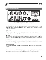
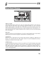
LOW CUT switch
This switch places a 12 dB per octave shelving high pass filter in the signal path. The knee frequen-
cy of the Low Cut filter is 75 Hz. This filter is very useful for removing low frequency rumble or han-
dling noise from a microphone input signal. It is also good for reducing the very low frequency com-
ponents of signals that can damage speakers or use up amplifier power unnecessarily.
LEVEL control
This control determines the output level of the preamp section of the 576. It is used to moderate sig-
nal levels produced by the tube drive and EQ circuits. There is +/- 15 dB of gain control available.
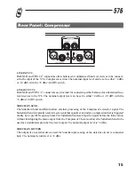
LIMIT led
This led illuminates when the output signal exceeds the level set by the Threshold control and it indi-
cates that PeakPlus
ª
limiting is occurring.
PeakPlusª Limiter THRESHOLD control
This control sets the threshold level at which the PeakPlus
ª
Limiter circuit becomes active. The
threshold range is from 0 dBu to +22 dBu (off). The PeakPlus
ª
Limiter stage is a unique program
Limiter featuring Intelligent Predictive Limiting
ª
. Its function is to monitor the input signal and
intelligently predict the amount of gain reduction needed to keep the output signal below the ceiling
set by the PeakPlus
ª
control.
Note that since the PeakPlus
ª
Limiter is a fail-safe Limiter it must come after the Output Gain con-
trol. If the Output Gain is set too high as compared to the PeakPlus
ª
Level control, continuous lim-
iting can occur. While PeakPlus
ª
is typically used as a protective function, creative effects can be
achieved by intentionally driving the signal into heavy PeakPlus
ª
limiting.
Great care has gone into the design of the PeakPlus
ª
Limiter to keep it acoustically transparent.
Appropriate use of it can protect your gear while keeping the signal free of artifacts. Peak Plus
ª
also
serves to prevent digital overload when used in conjunction with the dbx Type IV
ª
Conversion
System option.
DRIVE LEVEL switch
This configures the meter to show the signal level at the input to the vacuum tube. Note that high gain
settings can result in excessive movement of the meter as the needle contacts the endpin. In this sit-
uation itÕs best to briefly check the drive level and then switch to one of the other meter modes.
7