dbx 576 Owner'S Manual Download Page 13

Compressor Controls (cont.)
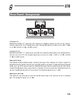
RELEASE control:

The Release control sets how fast the compression circuit returns the input to its original level. The
release rate is from 250 dB/sec where compression follows the envelope of the program material very
tightly to 5 dB/sec for very smooth compression.

UNLINK Switch:

This switch determines whether the input to the Compressor section comes from the CompressorÕs
line input jack or from the output of the 576Õs Preamp. This is a convenience feature to allow you to
use the Preamp and Compressor as two independent processors if desired. When activated, this
switch unlinks the normal connection between the output of the Preamp and the input of the
Compressor. When de-activated, the Preamp and Compressor are placed in series for processing a sin-
gle signal source.

DRIVE control

This control sets the amount of gain that will be applied at the input of the vacuum tube stage present
in the Compressor section. When the 576Õs Compressor section is used independently of the Preamp
section, this control offers tube drive control (with its sonic stamp) to any signal routed through the
Compressor. When the Preamp and Compressor sections are connected in series a high Drive control
setting can be used in conjunction with a high drive setting on the Preamp section to offer Òover-the-
topÓ distortion effects.

SC (SIDECHAIN) ENABLE switch

This switch enables the Sidechain processing loop. The Sidechain in and out connectors on the 576
rear panel allow external processing of the CompressorÕs detector signal. This switch has no effect if
there is nothing plugged into the Sidechain loop even though the switch will light when pressed. For
more discussion of the Sidechain see page 16.

SC (SIDECHAIN) MON switch

This switch allows you to monitor the sound of the Sidechain processing. The switch will light when
pressed to indicate that you are listening to the Sidechain; not the main signal path.

CONTOUR switch

This switch adds a gentle low frequency de-emphasis into the detector path (this is identical to hav-
ing an equalizer in the Sidechain loop, only weÕve done it for you). This is extremely useful in keep-
ing low frequency program material from ÒmufflingÓ or Òpunching holes inÓ the compressed signal.
This feature allows faster attack times and higher compression ratios with less artifacts. The switch
will light indicating contouring is activated.

11

Summary of Contents for 576

Page 1: ...Vacuum Tube Preamplifier Compressor Owner s Manual Version 1 0...

Page 2: ...ire shall be connected directly to the unit s chassis WARNING If the ground is defeated certain fault conditions in the unit or in the system to which it is connected can result in full line voltage b...

Page 3: ...ble of Contents Introduction 2 Features 2 Inspection 3 Warranty 3 Connections 4 Preamp Controls 5 Compressor Controls 10 Rear Panel Preamp 14 Rear Panel Compressor 16 Specifications 17 Settings Page 2...

Page 4: ...limiting and the advanced dbx V1 VCA module that ensures high system performance Precision 1 resistors are used through out the audio path to ensure performance stability and low noise To ensure year...

Page 5: ...oduct loss of parts or con necting the product to any but the specified receptacles This warranty is void unless service or repairs are performed by an authorized service center No responsibility is a...

Page 6: ...and 1 4 TRS connectors on the inputs and outputs can be used for bal anced or unbalanced connections However the use of more than one connector at a time on the input pair could unbalance balanced lin...

Page 7: ...This control varies the gain of the mid frequency equalization the gain range is 15 to 15 dB The mid frequency filter is a bandpass configuration with variable frequency and switchable bandwidth NARR...

Page 8: ...moderate settings of the Drive and Level controls if a high degree of tube saturation is desired this result can be obtained by using higher settings of the Drive control in conjunction with lower se...

Page 9: ...featuring Intelligent Predictive Limiting Its function is to monitor the input signal and intelligently predict the amount of gain reduction needed to keep the output signal below the ceiling set by t...

Page 10: ...dBu a meter read ing of 0 VU corresponds to 4 dBu output When the rear switch is set to 10 dBV a meter reading of 0 VU corresponds to 10 dBV output DITHER switch This switch becomes active only when...

Page 11: ...luminates when the signal is below the level set by the Compressor Threshold control This indicates that the Compressor is not compressing and is operating in its linear region THRESHOLD control This...

Page 12: ...very fast attack setting will cause the 576 to act like a peak Limiter even though RMS average level detection circuitry is used Slower attack settings cause the 576 to act like an RMS or averaging d...

Page 13: ...ny signal routed through the Compressor When the Preamp and Compressor sections are connected in series a high Drive control setting can be used in conjunction with a high drive setting on the Preamp...

Page 14: ...kPlus limiting circuit DRIVE LEVEL switch This configures the meter to show the signal level at the input to the vacuum tube Note that high gain settings can result in excessive movement of the meter...

Page 15: ...mic requires phantom power ensure that the phantom power switch on the front panel is turned off before connecting your mic LINE INPUTS Both XLR and 1 4 TRS connectors are provided to allow balanced o...

Page 16: ...rect post preamp output that bypasses the EQ and main output stages of the 576 The Send is post preamp and the Return is pre EQ Both the Send and Return are balanced TRS jacks with 4 dBu nominal sensi...

Page 17: ...Bu 10 dBV switch SIDECHAIN SEND The Sidechain Send and Return allow external processing of the Compressor s detector signal The Sidechain Send is typically used to feed an external equalizer to produc...

Page 18: ...or 470k unbalanced with rear panel INST switch engaged Maximum Input Level 30 dBu or 22 dBu with rear panel INST switch engaged Outputs Connectors Male XLR Pin 2 hot and TRS 1 4 Type Servo balanced un...

Page 19: ...rogram dependent Typically 250 dB sec to 5 dB sec Auto Attack Time Program dependent Typically 15ms for 10 dB 5ms for 20 dB and 3ms for 30 dB Auto Release Time Program dependent Typically 125 dB sec r...

Page 20: ...Hz to 20 kHz Interchannel Crosstalk Typically 98 dB 20 Hz to 20 kHz POWER SUPPLY Operating Voltage Switchable between 100 120 230 and 240VAC 50 60 Hz Power Consumption 30 Watts max Fuse 100 120V 500mA...

Page 21: ...19 dbx 576 Settings Page Photocopy this page and mark the settings you use for your sessions Session Date Comments Session Date Comments...

Page 22: ...South Sandy Pkwy Sandy Utah 84070 Phone 801 568 7660 Fax 801 568 7662 Int l Fax 603 672 4246 Questions or comments E mail us at customer dbxpro com or visit our World Wide Web home page at www dbxpro...

Reviews: