background image

ROIP302 Series User menu 


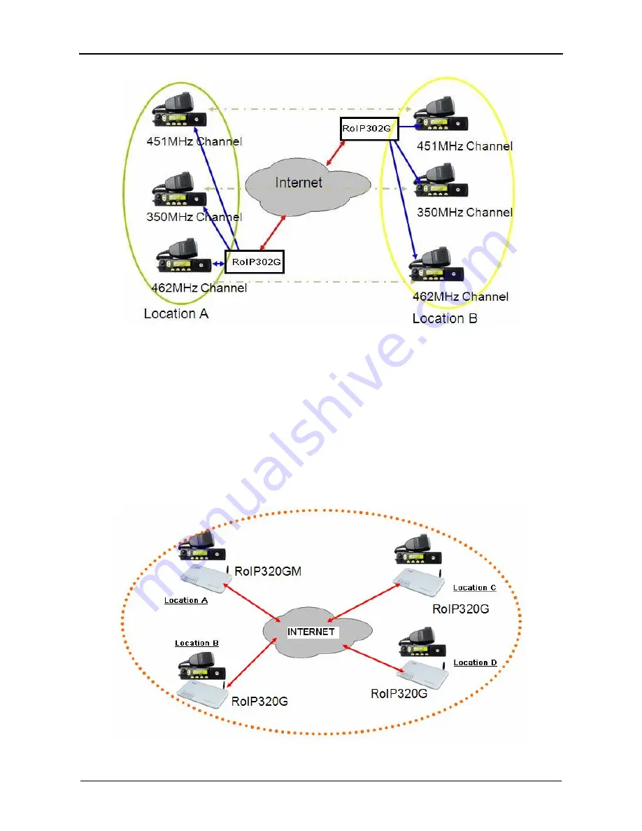
Application example 2: Link up radio network at multiple locations 

-  As shown in the application diagram above, four locations can be linked up via one 

RoIP302GM and three RoIP302G.      The RoIP302GM has a built-in SIP server and the group 

transmit capability to up to 12 SIP clients.      By replacing one RoIP302G with RoIP302GM, 

the system is now in Group Transmit Mode and up to 11 more RoIP302Gs can be added to 

the system.      Each RoIP302G now registers to the RoIP302M.   This mechanism allows the  

system to expand rapidly.   


www.dbltek.com  

Summary of Contents for ROIP302 Series

Page 1: ...enu Cross Network Gateway Radio VOIP GSM Public Announce User Manual ROIP302 Series Version 1 0 2010 7 13 For environmental protection please view this manual electronically and only print the pages you need www dbltek com ...

Page 2: ...t Box Check List 3 Overview 4 Installation 5 Default Factory Settings 6 Web Configurations 7 Call Settings 8 Operating Instructions 9 Application Examples 10 Hardware Specifications 11 Software Specifications 12 Miscellaneous 13 Troubleshooting www dbltek com ...

Page 3: ...NS service For testing purpose this DDNS service is temporary provided for free by DBL Technology Hong Kong However this service is not guaranteed without any interruptions Customers are urged to build their own DDNS server or obtain this service from a DDNS provider Free DDNS server software may be obtained freely from your local network service provider 4 Customers and or users are taking full r...

Page 4: ...ROIP302 Series User menu 1 2 3 4 1 x Main Unit 1 x AC DC Adapter Input 110 220VAC Output 12VDC 2A 3 x PTT Adapter Cables 1 x Ethernet Cable www dbltek com ...

Page 5: ...network with extended coverage and an integrated network of multiple amateur radio networks RoIP302 Series Cross Network Gateway has 3 PTT interfaces Up to 3 audio channels from radio networks can be connected to the RoIP302 simultaneously All 3 channels can be programmed into the same or different groups in order to bridge real time voice communications to various network interfaces RoIP302 Serie...

Page 6: ... two radio terminals 3 2 Modes of Operation With different options RoIPs support both Point to Point Mode and Group Transmit Mode operations Please refer to Section 3 4 for more RoIP versions available There are two types of RoIPs RoIP302 and RoIP302M RoIP302s cannot only support Point to Point operation RoIP302M has a built in SIP server for 12 clients RoIP302 can only support one client and grou...

Page 7: ... the Group Transmit mode This RoIP302M is the master with its own unique Group SIP Number and offers its built in SIP server for up to 12 RoIP302s RoIP302M can also register as well for expansion to register The diagram below shows only RoIP302s are used to register to the RoIP302M Each RoIP302s must have its unique Group SIP Number A maximum of 12 RoIP302s can be deployed in this example Please n...

Page 8: ...t the user needs to insure sufficient bandwidth is available and the network connection is stable before implementing a large network In general intranet network is preferred in this case 3 3 Application Examples Application example 1 Link up radio network between two locations Using two RoIP302Gs to link up three radio channels in two different locations www dbltek com ...

Page 9: ... RoIP302GM and three RoIP302G The RoIP302GM has a built in SIP server and the group transmit capability to up to 12 SIP clients By replacing one RoIP302G with RoIP302GM the system is now in Group Transmit Mode and up to 11 more RoIP302Gs can be added to the system Each RoIP302G now registers to the RoIP302M This mechanism allows the system to expand rapidly www dbltek com ...

Page 10: ... Power Description Remote control Relay switch with 220VAC input and 500 mA load current 6 pin RJ11port for PTT Adapter Cable 6 pin RJ11port for PTT Adapter Cable 6 pin RJ11port for PTT Adapter Cable Press 10 seconds to reset the device to factory defaults 10 100Base T WAN connection for external access 10 100Base T LAN connection 12V 1A www dbltek com ...

Page 11: ...e data transmissions PC port status Lights up when the PC port is connected Blinks when there are data transmissions Channel 1 Channel 2 Channel 3 GSM Channel 1 Tx Rx status Channel 2 Tx Rx status Channel 3 Tx Rx status GSM status Channel 1 is receiving transmitting Channel 2 is receiving transmitting Channel 3 is receiving transmitting A GSM call is active c Channel Port Pin Assignment The channe...

Page 12: ...d Please the SIM card properly with the cut corner pointing to the edge of the device Place the clip over the SIM card and then slide it forward to lock the clip g Main Unit Setup i Connect the Switch Port to an external system for remote control It can be used to switch on and off a Public Announce PA system to instant broadcast If the relay switch is connected to high voltage load The maximum ra...

Page 13: ...nsure the best voice quality 5 Factory Default Settings The table below shows the factory default settings There are two ways to reset to the factory default settings i Press the RESET switch for more than 15 seconds ii In the Configuration page select Tools and then Reset Config Item Login ID Login Password WAN Port Setting LAN Port Setting PTT State GSM Login password PTT maximum duration Jitter...

Page 14: ... window is then displayed Enter the User name and the Password now The user name for the administrative level is admin and the default password is admin Please make sure to click on Save Changes after configuring the device Method 2 is to access the built in web server via the WAN port The WAN port is set to DHCP mode as a default factory setting When it is first connected to a network with a DHCP...

Page 15: ...ver It consists of three columns and it is important to understand the information shown in this page in order to debug or report a device problem 1 Left hand column shows the device information and the SIP registration status 2 Middle column shows information on the network configuration and its status 3 Right hand column shows information on the GSM hardware carrier and channel status www dbltek...

Page 16: ...the voice prompts Currently only English and Simplified Chinese are supported 2 Time Zone and Time Server Time Zone is specified as GMT or a fixed value RoIP acquires the standard GMT time from the Time Server specified 3 Auto Reboot This option reboots the device automatically at the time specified 4 DDNS When the RoIP is installed in a network environment with dynamic IP and a SIP server is not ...

Page 17: ...RoIP302 depends greatly on the bandwidth usage In this case it is best to configure the router to DMZ mode to the IP of the RoIP302 In order to get network access the LAN port must be configured according to the network environment to be connected There are 3 access methods available for the LAN port configuration 1 Static IP This mode applies to both public and private IP network environment In t...

Page 18: ...GoIP4 Gateway In this case the GoIP4 Gateway functions as an Ethernet Switch 2 Static IP Mode Default Setting Select Static IP mode for a new network segment on PC port In this case the GoIP4 Gateway functions as Router Enter the IP address in IP Address field with a new segment address that is different from that on the LAN port Enter the subnet mask in Subnet Mask field accordingly A commonly us...

Page 19: ...trator If a peer to peer configuration is used then this number must be unique and is assigned by the user arbitrary For SIP Proxy mode each RoIP302 are designated as a terminal The table below describes how to program the key parameters Other parameters should be programmed as required by the SIP proxy SIP Proxy Mode Settings RoIP302 Terminal Group SIP Number SIP Proxy Auto Dial Number Assigned b...

Page 20: ...n defines the PPT Signal settings RoIP302 supports up to 3 PTT ports and each PPT consists of two control signal PTT Input and Output Difference radio terminals may have different requirement on the PTT control signals Please consult the User Manual of your radio terminal for more information 1 Input Active Level defines the active level for the PTT Input Select 1 if the PTT Input is active when t...

Page 21: ...mation 6 9 Public Announce PA Settings The RoIP302 provides a relay switch to control a PA system When the RoIP302 receives the PA ON Password it turns on the relay to activate the PA system Audio is transmitted to the PA system at this time When the RoIP302 receives the PA OFF Password it turns off the relay to deactivate the PA system The duration for the relay to be in the ON state is limited b...

Page 22: ... that all users in the same group must use the same codec 6 11 Group Settings The Group Settings assigns the radio channels 3 PTT Ports and the GSM channel to one of the three groups available Once a channel is assigned it cannot be assigned to another group In the diagram below all 4 channels are assigned to Group 1 This means that there are no channels left for Group 2 and 3 In this case RoIP302...

Page 23: ...ed in Section 7 7 and then press the key The default password is 123 Once the correct password is entered RoIP302 generates double beeps as confirmation The caller can then hear the voice communications of the group that the GSM Channel is assigned to Please note that only one way voice communication is allowed The caller should wait for a silent period before enabling the voice channel to talk To...

Page 24: ...ample 1 Linking up two MOTO GM300 Radio terminals in peer to peer mode with two RoIP302 RoIP302G The network access method is ADSL Operating procedures 1 Connect the PTT Interface of the radio terminal GM300 with the PTT Interface Cable as shown in the diagram below Connect the RJ 11 plug of the PTT Interface Cable to PTT1 port of the RoIP302 2 Connect the RoIP302 LAN port to an Ethernet port of t...

Page 25: ... the DDNS feature If the serial number of the RoIP302 is RoIP30220100610005 then the DDNS settings are shown below 9 Next go to Call Settings page and configure it as shown below 10 Configure the Group Settings as shown below Since the PTT Interface Cable is connected to PTT1 port and there are no devices connected to PTT2 and PTT3 ports only PTT1 port is assigned to Group 1 Select the GSM channel...

Page 26: ...own below Please note that it has a different Group SIP Number as the one in location A Please note that the SIP Proxy address is set to the DDNS of the RoIP302 at location A The Auto Dial Number is set to the Group SIP Number of the one at location This means that 102 calls 101 automatically whenever the PTT control is active transmitting voice from 102 to 101 14 Please note that the Network Sett...

Page 27: ...M300 radio terminals as users Setting up RoIP302M 1 The hardware setup of GM300 is the same as the one shown in Example 1 2 Connect the PTT Interface of the ICOMIC 2720 with the PTT Interface Cable supplied as shown in the diagram below Connect the RJ 11 plug of the PTT Interface Cable to PTT1 port of the RoIP302M 3 Assuming the public IP for the RoIP302M is 202 96 123 123 Its Network Settings sho...

Page 28: ... clients referred as Soft Lines here and onboard channels PTT1 PTT2 PTT3 GSM Similar to RoIP302 each onboard channel can only be assigned to one group RoIP302M can at the most accept up to 12 client registrations This means that these 12 clients Soft Lines are split among the 3 groups In the example below 12 Soft Lines are assigned to Group 1 and this means that there are no more lines available f...

Page 29: ...o the Group SIP Number of the RoIP302M This is the number to be called when the GM300 Radio is talking 6 The Group Codec Setting must be set to G 729 7 Repeat the above with other RoIP302s and a RoIP network with a maximum of 13 locations can now be achieved 8 If more locations are needed it is possible to connect another RoIP302M to the master RoIP302M Then more RoIP302s can then be connected to ...

Page 30: ...n CPU ARM9 RAM 16MB FLASH 4MB DSP 116 MHz 16 Bit Bus 3 PTT Interface PTTIN Active Low 0 7V 4 7KΩ load PTTIN Active High 1 2V PTTOUT High Output 5V 4 7 KΩ load PTTOUT Low Output 0V APUT Output 8Ω 750mW 5V P P AIN Input 600Ω Internal Impedance 0 0 6Vp t p ADJOUT on the Adapter Cable 2KΩ Potentiometer RAM 16MB PTTIN Circuit Based on the circuit above the PPT Input level is high when it is open ended ...

Page 31: ...s 1W at DCS1800 and PCS1900 5 Network Port Ethernet Port 10 100 Base T Standard Supported IEEE802 1p IP Standard IPV4 6 Firmware Item Description Remark OS Linux Version 2 6 IP Voice Protocol SIP 2 0 Include SIP INFO extension Network Protocol IP TCP UDP HTTP ICMP DHCP CL SRV NTP TFTP ToS telnet Codecs Configuration GUI G 711 a μ G 729A G 729AB G 723 1 GSM Html XML2 0 JAVA www dbltek com ...

Reviews: