background image

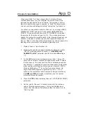
After calibrating your 4030's "live" input channel (No. 1), you should set
the high and low endpoints for the individual BARGRAPH display of
Channel 5 ("LIVE" INPUT WITH TARE), using the procedure given
below.  This same procedure may be used to scale the bargraph dis-
play of any of the other 4030 data channels listed in Section 1.d.  For
the relation of BARGRAPH endpoint values to the other four limit-zone-
defining parameters, see Fig. 8 in the next section.

1.

Display Channel 5 (see Section 2.d).

2.

Following the general procedure explained in Section 1.f, enter
"SETUP" mode and step to the "LEP" (LOW ENDPOINT)
parameter.

The initial "LEP" setting for Channel 5 is normally "-1.000."  THIS
WILL HAVE BEEN AUTOMATICALLY SCALED, HOWEVER, SO
THAT ITS DECIMAL-POINT LOCATION MATCHES THAT OF THE
SCALING FACTOR ("F1") YOU ENTERED WHEN YOU CALI-
BRATED CHANNEL 1 IN SECTION 2.e.  If, for example, your "F1"
value for Channel 1 was "XXX.X" (where "X" is any number), the
displayed "LEP" value for Channel 5 will be "-100.0."  The
decimal-point position will always be the same for all six limit-zone
parameters ("LEP," "LLL," "LOL," "HIL," "HHL," and "HEP").
As mentioned in Section 1.f, 

this position cannot be changed, since

it depends directly on the precision of the last "F1" entry.

3.

Using the "ARROW" buttons as explained in Section 1.f, enter the
desired LOW ENDPOINT value for the bargraph display of Chan-
nel 5, as expressed in the engineering units selected for that
channel.

4.

Press the STEP button five times.  The "HEP" parameter should
now be displayed.  Enter the desired HIGH ENDPOINT value for
the bargraph display of Channel 5 (again, as expressed in the
engineering units selected for that channel).  The initial "HEP"
setting for Channel 5 is normally "1.000."

The "LEP" and "HEP" values for a given channel may be any numeric
constants from -32768 through 32767, provided that the "LEP" value is
less than the "HEP" value.  At least 51 units (absolute count) must
separate the HEP and LEP values.

Scaling the Bargraph Display

2.g

2.12

Summary of Contents for 4030

Page 1: ...MODEL 4030 SINGLE CHANNEL AC LVDT INSTRUMENT SB 5 4000 Instrument Series INSTRUCTION MANUAL...

Page 2: ...reprinted reproduced or used in any form or by any electronic mechanical or other means including photocopying and recording or in any information storage and retrieval system without permission in wr...

Page 3: ...MODEL 4030 SINGLE CHANNEL AC LVDT INSTRUMENT INSTRUCTION MANUAL Model 4030 Instruction Manual v SB 5 Pub No 4030M 5 Issued 10 96 Part No 91472 Daytronic Corporation Dayton OH www daytronic com...

Page 4: ......

Page 5: ...LCD Viewing Angle 2 8 d Selecting a Channel for Display 2 9 e Channel Calibration 2 10 f Setting Channel Filters 2 11 g Scaling the Bargraph Display 2 12 h Defining Limit Zones 2 13 i Logic I O Conne...

Page 6: ...ent bargraph with end point indication Backlit 0 6 inch LCD with adjustable viewing angle and limit triggered flashing Independently settable dual limit displays RS 232 C I O Port for optional keyboar...

Page 7: ...EIGHT REAR PANEL LOGIC I O A full listing of your 4030 s standard configuration is given in Appendix A Like all 4000 Series instruments however the 4030 can be rapidly and easily reprogrammed in the...

Page 8: ...t any one or a combination of given legends and indicators See Appendix C for Legend and Indicator Annunciation Appendix D describes a special calibration procedure that may be applied to a nonlinear...

Page 9: ...following calibration Gain Stability vs temperature 50 ppm C vs time 20 ppm month Filter per channel 3 pole modified Butterworth 3 dB down at 10 Hz 60 dB down at 100 Hz Step Response Settling Time Ful...

Page 10: ...al Function Buttons Engineering Unit Legends Channel No and Mnemonic Display mm SET UP Bargraph High Endpoint HEP High High Limit HHL Low Limit LOL High Limit HIL Button RUN TIME FUNCTION Indicators B...

Page 11: ...O Analog Input Connector see Figs 5 6 Logic I O Connector see Figs 4 9 ON OFF Switch Fuse AC Power Connector Connector for Optional Keyboard Voltage Selector Switch RS 232 C Interface Connector see Ap...

Page 12: ...g 10 1 O Analog Input Connector see Figs 5 6 Logic I O Connector see Figs 4 9 ON OFF Switch Fuse Connector for Optional Keyboard RS 232 C Interface Connector see App B DC Power Connector see Fig 7 Pan...

Page 13: ...two rear panel CLAMP SCREWS and slide the CLAMP SLIDES rearwards out of their grooves Insert the 4030 unit through the panel cutout from the front of the panel if the unit has rubber feet these will...

Page 14: ...MIN RESET button 7 MINIMUM VALUE OF CHN 5 This channel represents the least positive value of Channel 5 since MIN measurement was last reset via the front panel MAX MIN RESET button 8 MAX minus MIN V...

Page 15: ...motors or pumps initiate and control safety shut down sequences and perform many other automation tasks that require intelligent switching even of substantial amounts of power These are nonlatching ou...

Page 16: ...erminal 3 will be at a Logic 1 0 V DC level whenever the reading of Channel 5 is greater than or equal to the current LOL limit value and less than or equal to the current HIL limit value for that cha...

Page 17: ...ence the existing numeric configuration parameters of any selected channel At the same time you can easily reset any displayed parameter to any allowable value The LEFT ARROW button lets you select a...

Page 18: ...he mnemonic of the parameter presently under consideration On exiting SETUP the smaller display will show the number of the channel currently displayed by the main LCD 2 Selecting a Channel for Setup...

Page 19: ...ing parameters see the optional System Instruction Manual Channel Configuration Parameters DIS DISPLAY Section 2 d LCT LOCATE LNS LINEARIZATION SEGMENTS F0 FIRST CALIBRATION POINT Section 2 e F1 SECON...

Page 20: ...ctive changeable digit You have the option of changing the value of the active digit as explained in Step 5 or of activating the next digit to the left To move the active digit one digit to the left P...

Page 21: ...splayed number is 990 the active digit being the second from the right and the UP ARROW button is pressed once the resulting number will be 1000 Note that the original active digit will continue to fl...

Page 22: ...a single flashing decimal point appears in the desired position the DOWN ARROW button can here be used to move the decimal point to the right if necessary To change the position of an existing decima...

Page 23: ...its battery every time the unit is turned on If on powerup the battery is found to be below 3 0 V DC the front panel LCD will display a warning of LO bat Note that at this level the battery will stil...

Page 24: ...rtion With regard to 4030 transducer cabling please note the following 1 5 wire LVDT cabling Fig 6 a or 3 wire variable reluctance transducer cabling Fig 6 c is to be used when the cable is under 20 f...

Page 25: ...l labelled HI SIG instead of to the SIG terminal Similarly you would connect the SIGNAL line to the terminal labelled HI SIG instead of to the SIG terminal 4 When wiring a variable reluctance transduc...

Page 26: ...TR WIRE SENS EX EX SENS SHLD HI SIG HI SIG Fig 6 a 4030 Transducer Cabling 5 Wire LVDT Cabling under 20 ft in length For Long Stroke LVDT s LVDT INPUT SHIELD SENSE SENSE EXCITATION EXCITATION SIGNAL P...

Page 27: ...EX SENS SHLD HI SIG HI SIG Fig 6 c 4030 Transducer Cabling 3 Wire Variable Reluctance Cabling under 20 ft in length LVDT INPUT SENSE SENSE EXCITATION SIGNAL EXCITATION SHIELD SIGNAL 10K 10K SIG SIG CN...

Page 28: ...ver to turn the fuse slot counterclockwise and the fuse will spring out IN THE EVENT OF AN APPARENT POWER SUPPLY FAILURE FIRST CHECK THE FUSE WHEN REPLACING A BLOWN FUSE ALWAYS INVESTIGATE THE CAUSE O...

Page 29: ...d mild EMI a clean line is still very desirable No protection is provided against dropout longer than 8 milliseconds or brownout below 90 volts Depending on your line conditions a number of protective...

Page 30: ...d either to the negative terminal of the vehicle battery or directly to the vehicle chassis IT SHOULD NEVER BE LEFT UNCONNECTED ALSO TO MINIMIZE NOISE PICKUP THE GROUND LEAD SHOULD BE AS SHORT AS POSS...

Page 31: ...ause the display to disappear and you will then have to lower the angle somewhat Step 3 Also note that it usually takes about three seconds before you see any real change in the display 3 If you wish...

Page 32: ...hannel number will continue to flash in the small mnemonic display under the engineering legends 3 Again PRESS THE BUTTON The number of the displayed channel should now appear in the mnemonic display...

Page 33: ...1 see Section 2 d 2 Following the general procedure explained in Section 1 f enter SETUP mode and step to Channel 1 s F0 parameter 3 Set the load for Channel 1 s transducer equal to the minimum value...

Page 34: ...increasing amounts of automatic digital filtering Channel 1 is normally preset to a filter setting of 3 4 Exit SETUP mode by pressing the SETUP button 6 Now enter the numerical value of the second kno...

Page 35: ...or Channel 1 was XXX X where X is any number the displayed LEP value for Channel 5 will be 100 0 The decimal point position will always be the same for all six limit zone parameters LEP LLL LOL HIL HH...

Page 36: ...Display 2 h Defining Limit Zones Once you have set the endpoints of Channel 5 s bargraph display you can define seven discrete limit zones with respect to that bargraph as shown in Fig 8 BELOW BARGRA...

Page 37: ...it is in the current SAFETY NO VIOLATION ZONE from Terminal 4 when it is in the current UPPER CAUTION ZONE from Terminal 5 when it is in the current UPPER DANGER ZONE and from Terminal 6 when it is in...

Page 38: ...Logic I O Connector OPEN LOGIC 0 CLOSED LOGIC 1 N 5 GD 0 7 AAAAAA AAAAAA AAAAAA AAAAAA AAAAAA 4 3 AA A A AA AA AA AA AA AA AA A A AA AA AA AA AA AA A A AA A AA AA AA A A AA AA A A AA 2 1 Model 9398 93...

Page 39: ...lacement reading in inches mm etc which you want the full scale output to represent The m value should reflect the precision that currently applies to Channel 5 this is initially the nearest thousandt...

Page 40: ...No 4 MAX MIN MAX MIN STEP Each Push If Channel 5 is currently on display displays Channel 6 MAXI MUM VALUE OF CHANNEL 5 and lights the F3 indicator If Channel 6 is currently on display displays Chann...

Page 41: ...N A N A 8 F1 1 1 000 0 000 N A N A N A 9 00 1 5 000 0 N A N A N A 10 00 1 5 000 0 N A N A N A 11 00 1 5 000 0 N A N A N A 12 00 1 5 000 0 N A N A N A 13 00 1 5 000 0 N A N A N A 14 F6 1 1 0 N A N A N...

Page 42: ...9 N A N A N A N A N A N A N A CALCULATION CHANNELS Channel No CLC 4 1 CHN4 0 5 1 CHN1 CHN4 0 000 6 1 000 MAX CHN5 0 000 7 1 000 MIN CHN5 0 000 8 1 000 CHN6 CHN7 0 000 14 1 CHN14 0 15 1 CHN14 0 16 1 CH...

Page 43: ...N A 3 CHN4 CHN1 4 INC14 SDI 5 CHN6TO7 CHN5 ANNUNCIATION Annunciator Number ANN 1 1 2 6 0 7 1 8 0 LOGIC I O Bit Number LIO 0 7 OUT LOGIC SOURCES Bit Number SRC 0 6 LIM NON 7 10 EXT NON 11 LIM NON 12 E...

Page 44: ...DLY 0 CMT 0D OPT 00 0D EOT 00 0D OTHER GENERAL SETUP PARAMETERS SCN 1 19 TER 19 EXC 5 SBC 1 ASN 0 LGO 4030 STANDARD EDT Y DIS 5 BAR DIS BEP LEP FLA 1000 CPC 9 CLM 1 PKN HLD PKP HLD XBG1 1 XBG2 2 SHP...

Page 45: ...ggested cabling between a 4030 and a computer terminal printer etc that uses a 9 Pin D Subminiature Connector for its RS 232 C interface such as an IBM PC AT Please note that the cabling in Figs 11 an...

Page 46: ...2 3 4 5 6 7 8 9 4000 Instrument Required for connection of the 4000 instrument to an IBM or IBM compatible computer but not to a Daytronic Model PC HSICA Male connector required for Model PC HSICA Fig...

Page 47: ...DTR COMMON CTS TRANSMIT RECEIVE RTS CTS COMMON DTR COMPUTER NO HANDSHAKE 4000 Instrument 11 c 9 Pin RS 232 C Connector 2 3 4 5 8 2 3 4 5 6 8 RECEIVE TRANSMIT DTR COMMON CTS RECEIVE TRANSMIT DTR COMMO...

Page 48: ...gends and or indicators to light up at any time when instrument power is on you can use the ANNUNCIATOR ANN command The front panel annunciators consist of the indicators that correspond to the first...

Page 49: ...tion 2 d 2 Following the general procedure explained in Section 1 f enter SETUP mode and step to Channel 1 s LINEARIZATION SEGMENTS LNS parameter the 4030 s initial LNS setting is 1 3 For the LNS valu...

Page 50: ...ould first divide this range into approximately equal segments the number of segments being the number entered for LNS in Step 3 above 9 To define the linear segment from F0 to F1 use the ARROW button...

Page 51: ...pressed to the nearest hundredth of an inch e g 1 00 The 4030 s display of any channel based on Channel 1 will then reflect this precision 11 Continue to enter as many LINEARIZATION POINTS as you spec...

Page 52: ...THAT MIGHT HARM THE 4030 S MICROPROCESSOR IF POS SIBLE WORK ON AN ANTI STATIC SURFACE AND WEAR A GROUNDING STRAP AROUND YOUR WRIST THE STRAP SHOULD BE CONNECTED TO EARTH GROUND 3 Unscrew the two rear...

Page 53: ...attery out of its clip socket IMMEDIATELY INSERT THE NEW BATTERY INTO THE SOCKET BEING CAREFUL TO OBSERVE THE CORRECT POLARITY OF THE TERMINALS A backwards battery won t damage the 4030 but it won t w...

Page 54: ...Daytronic Corporation Dayton OH 800 668 4745 www daytronic com...

Reviews: