


Potentiometer Port Configuration in SigmaStudio
There is some configuration within SigmaStudio required so the ADAU1701 knows to interpret each
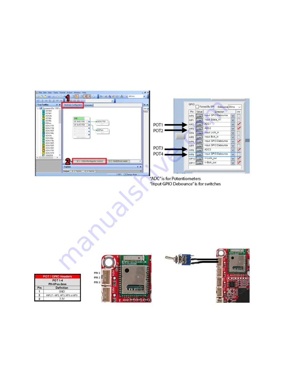
multipurpose (MP) pin as a potentiometer input or button/switch input. Simply open the hardware
configuration menu, then select the “IC 1 –
170x\140x Regist
er Control” tab. Configure the MP pin that
corresponds to your potentiometer header to “Input GPIO Debounce” for a button/switch, or “ADCX”
for a potentiometer. (POT4 will actually be represented as ADC0, not ADC4).
Any example project from Dayton Audio that you use will already have this preconfigured.
Using the Potentiometer Ports for Connecting Buttons or Switches
The 4 potentiometer ports on the boards are optimized for potentiometers, however they can be easily
used to instead connect buttons or switches to the ADAU1701, as they expose 4 of the multipurpose
pins of the ADAU1701. Simply connect your switch to the GND and MP pin of the desired potentiometer
port (Pin 1 and Pin 2 on the diagram below). Even though these are 3 pin headers, the 2-pin connector
that comes attached to the LEDs, Bluetooth pairing button, etc will also fit, just not perfectly. There is a
switch that comes in the optional KABD cable pack pre-wired to a 2-pin connector.


