background image

Page 5

For technical questions, please call 1-888-866-5797.

Item 58986 


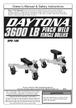
5.  Make sure one end of the Chain is secured 

to the Lock Pin. Loop the Split Ring through 

the hole on the end of the lock Pin. 

6.  Attach the other end of the Chain to the 

Metal Loop on the Base. Loop the Split 

Ring through the Metal Loop.

Metal Loop

Split Ring

Chain

Lock Pin

Operating Instructions

  Read the ENTIRE IMPORTANT SAFETY INFORMATION section at the beginning of this 

manual including all text under subheadings therein before set up or use of this product.

WARNING!  TO PREVENT SERIOUS INJURY: Be 

ready for any movement the vehicle may make 

when the tires come off the ground.  Ensure that 

you have sufficient assistance and manpower 

to safely guide and control the vehicle.
WARNING!  TO PREVENT SERIOUS INJURY:


Stay clear of any sloping areas or entry ramps, 

however shallow they may appear.  Sufficient 

space should be allowed between the side of the 

vehicle and an adjacent wall for the vehicle to be 

withdrawn from its location in a sideways manner.

1.  Lift vehicle high enough to roll the Dollies underneath.

Note:

 Place one Dolly on each side of the 

vehicle body under the frame pinch weld.

2.  Remove the Lock Pin and raise the Saddle 

to the necessary height, then re-insert Lock 

Pin and secure with Loop Wire Lock.

3.  Align the Saddle opening with the pinch weld.
4.  Loosen the Saddle Bolts and open 

the Saddle wide enough for the frame 

pinch weld to fit into the openings.

5.  Begin slowly lowering the vehicle 

body onto the Saddles.

Note:

 Check that the pinch welds are properly lined up 

with the Saddle openings before lowering completely.

6.  Lower the vehicle completely.

7.  Secure the vehicle to the Dollies by 

tightening the Saddle Bolts.

8.  Lock the Casters when the Dollies are 

in thier final position by pressing all six 

Caster Locks into the “ON” position.

Summary of Contents for DPD-180

Page 1: ...When unpacking make sure that the product is intact and undamaged If any parts are missing or broken please call 1 888 866 5797 as soon as possible Copyright 2022 by Harbor Freight Tools All rights reserved No portion of this manual or any artwork contained herein may be reproduced in any shape or form without the express written consent of Harbor Freight Tools Diagrams within this manual may not ...

Page 2: ...loves during use 10 Keep clear of load s path while placing on and removing from dollies and while moving 11 Use as intended only Do not use for aircraft purposes Use only in pairs 12 Inspect before every use do not use if parts are loose or damaged 13 Be aware of dynamic loading Sudden load movement may briefly create excess load causing product failure 14 Assemble only according to these instruc...

Page 3: ... discussed in this manual cannot cover all possible conditions and situations that may occur The operator must understand that common sense and caution are factors which cannot be built into this product but must be supplied by the operator 29 Do not roll while loaded over rough surfaces such as concrete seams Use on flat level hard surface only Wheels may scratch or dig into less durable surfaces...

Page 4: ...le on a flat level hard and smooth surface 2 Attach each Caster to the Base with Caster Bolts x4 Washers x8 and secure with Caster Nuts x4 Note One washer under the bolt head another washer between nut and caster plate 3 Assemble Saddle Head Slide onto the Saddle Head using Saddle Bolts and Saddle Nuts 4 Insert Saddle assembly into the Base line up holes and slide Lock Pin into place Secure with L...

Page 5: ...eas or entry ramps however shallow they may appear Sufficient space should be allowed between the side of the vehicle and an adjacent wall for the vehicle to be withdrawn from its location in a sideways manner 1 Lift vehicle high enough to roll the Dollies underneath Note Place one Dolly on each side of the vehicle body under the frame pinch weld 2 Remove the Lock Pin and raise the Saddle to the n...

Page 6: ...LY THE MANUFACTURER AND OR DISTRIBUTOR HAS PROVIDED THE PARTS LIST AND ASSEMBLY DIAGRAM IN THIS DOCUMENT AS A REFERENCE TOOL ONLY NEITHER THE MANUFACTURER OR DISTRIBUTOR MAKES ANY REPRESENTATION OR WARRANTY OF ANY KIND TO THE BUYER THAT HE OR SHE IS QUALIFIED TO MAKE ANY REPAIRS TO THE PRODUCT OR THAT HE OR SHE IS QUALIFIED TO REPLACE ANY PARTS OF THE PRODUCT IN FACT THE MANUFACTURER AND OR DISTRI...

Page 7: ...embly Diagram Parts List Part Description Qty 1 Saddle Nut 2 2 Saddle Head Slide 1 3 Saddle Head 1 4 Lock Pin 1 5 Base 1 6 Chain 1 Part Description Qty 7 Caster with lock 3 8 Caster Nut 12 9 Flat Washer 24 10 Caster Bolt M10X35 12 11 Saddle Bolt M10X130 2 12 Rubber Pad 2 Assembly Drawing ...

Page 8: ...lusion or limitation of incidental or consequential damages so the above limitation of exclusion may not apply to you THIS WARRANTY IS EXPRESSLY IN LIEU OF ALL OTHER WARRANTIES EXPRESS OR IMPLIED INCLUDING THE WARRANTIES OF MERCHANTABILITY AND FITNESS To take advantage of this warranty the product or part must be returned to us with transportation charges prepaid Proof of purchase date and an expl...

Reviews: