


25
3. Put the repeater into Test Mode by turning on the repeater DIP Switch #4. When trying
to acquire stations, the repeater goes through the following process:
• It looks for a station signal for ten minutes, with the "STAT" LED flashing red
when it detects a signal not associated with a station during this time.
• It flashes yellow if it has found some stations but not all, and then;
• It flashes green when all stations are found. For each station found, the "TX" LED
flashes immediately after the "STAT" LED, indicating that it is transmitting the
station ID(s). See “Maintenance and Troubleshooting” on page 34 if the above
LED pattern does not display.
4. Turn repeater DIP switch #4 off once the test is complete, otherwise it will
significantly shorten battery life.
5. Close the repeater enclosure.
6. Select the second repeater in the chain (Repeater ID B) and put it in Test Mode. Also,
set it to receive any transmitter that is not already transmitting through repeater A. The
"STAT" LED displays the same light pattern during its acquisition phase as described
above.
Repeat the test process to verify communication for every repeater in the network.
Note: Each station that is transmitted through the repeater network must have its transmitter ID turned ON in
exactly one repeater. Its data automatically passes through each repeater in the chain to the receiver.
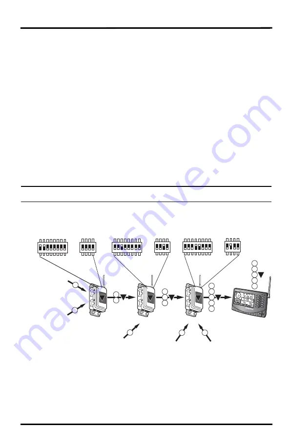
Use the following diagram to see the repeater and transmitter DIP switch positions in an
example combination network:
A
B
C
Repeater
Repeater
3
Repeater
1
2
1
4
5
4
3
2
1
5
Vantage Pro2
Console/Receiver
2
1
2
3
1
A
B
C
C
Transmitter DIP
Switch with
IDs 1, 2 ON
Repeater DIP
Switch set to ID A
Transmitter DIP Switch
with ID 3 ON
Repeater DIP
Switch set to ID B
Transmitter DIP
Switch with
IDs 4, 5 ON
Repeater DIP
Switch set to ID C
Vantage Pro2
Station
2
Leaf &
Soil Moisture
Station
Anemometer
Transmitter Kit
Temp/Humidity
Station
Temperature
Station
3
4
5
Summary of Contents for Envoy8X
Page 4: ......