Rev 0.11
Page G.703-10
Figure 3 - Balanced to unbalanced converter (Balun)
2.3.1.3.
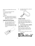
10/100 Ethernet (via the GbE- IP Connection)
The 10/100 Ethernet interface connector is used for SNMP control and monitor of the PSM-500
modem. Please refer to SnIP SNMP Guide for support information.
Table 3
GbE-IP Connector Pinouts (RJ45)
Name
Description
Pin
TX D1+
Transmit Data+
1
TX D1-
Transmit Data-
2
RX D2+
Receive Data+
3
BI D3+
Bi-directional pair C +
4
BI D3-
Bi-directional pair C -
5
RX D2-
Receive Data-
6
BI D4+
Bi-directional pair D +
7
BI D4-
Bi-directional pair D -
8
Figure 4 - Ethernet SNMP interface
2.3.1.4.
Console Connector
The console connector is available for command line control and monitor of the Optional G5
processor card.
Table 4
Console Connector Pinouts (9 pin D female)
Signal Name
Description
Direction
Pins
Notes
RXD
Console RX
From Modem
2
EIA 232
TXD
Console TX
To Modem
3
EIA232
GND
Ground
5
2.3.1.5.
USB2.0
The USB2.0 interface is reserved for future use.
3.0
G5 Interface Installation
The G5 interface is normally factory installed, but can be field installed by technical personnel.
The option card itself is an approximate 3.5-inch by 7.25 inch printed circuit board designed to be
mounted in the interface option position inside the PSM-500 series modem chassis.
Remove the modem unit from service before installation of the G5 Interface option. Unplug the
modem unit and remove the power cord from the rear for safety.
75 Ohm, BNC
Unbalanced I/O
120 Ohm, RJ-48
Balanced I/O