Neptune 5000
© Copyright Datem Limited 2014
79
Operational Information
When fitting a cone to a system, the power to the system should not be
switched on. This prevents any unbalanced-voltage supply damage during
fitting. While cones are not in use, the connector covers must be fitted to
protect from accidental damage to the connector pins. For removing and
fitting a cone to the cone-rod, the following procedures should be observed.
Cone Removal
1.
Firstly ensure the power is removed from the system, and
appropriate action is taken to prevent accidental energisation.
2.
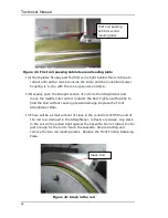
Remove the four retaining nuts on the black cone support block.
Slide the front half of the support block away from the cone.
3.
Holding the cone firmly, unscrew the crossover coupling while
applying light upwards pressure, until it is fully unscrewed. Gently
lower it until the connector is accessible, and then ease the
connector from the cone. Note that there is only approximately
40mm of free wire inside the end of the cone-rod, and attempting to
pull the cable out too far can damage the cable.
4.
Refit the cone’s connector cover, and place it in a transit case for
safety.
Cone Fitting
1.
Remove the cone from the transit case, making note of the serial
number on the end of the cone body. This is important to ensure
that when the system is operated, the automatic cone selection
function can be verified.
2.
Remove the connector cover, and store in the transit case. Check
that the o-ring on the back of the cone is in good condition. Gently
pull the small connector from the end of the cone-rod, taking care
not to pull the wire out too far.
3.
Orientate the male and female pins on the cone rod connector and
the cone connector, and push the two connectors together. Gently
push the cone up until the threads of the cone, crossover and cone-
rod touch.
4.
Applying light pressure upwards, rotate the crossover to draw the
rod and cone together.
5.
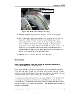
Replace the cone support block
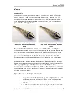
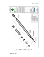
Where a cone is disassembled, all the o-rings should be replaced with new
ones. It is recommended to use a small amount of silicone grease on all o-
rings during assembly. It is of utmost importance to ensure that the tip o ring
behind the filter holder is fitted and that the tip is tight.
Summary of Contents for Neptune 5000
Page 1: ...Neptune 5000 Copyright Datem Limited 2014 1 Neptune 5000 Technical Manual ...
Page 14: ...Technical Manual 14 Figure 3 Topside Control Box Wiring Schematic ...
Page 15: ...Neptune 5000 Copyright Datem Limited 2014 15 Figure 4 Topside Control Box Wiring Layout ...
Page 30: ...Technical Manual 30 ...
Page 32: ...Technical Manual 32 Figure 14 Transformer Pod General Arrangement ...
Page 36: ...Technical Manual 36 Figure 15 Transformer Pod Schematic ...
Page 39: ...Neptune 5000 Copyright Datem Limited 2014 39 Figure 16 Electronics Pod General Arrangement ...
Page 44: ...Technical Manual 44 Figure 19 Neptune 5000 Electronics Pod Wiring Schematic ...
Page 51: ...Neptune 5000 Copyright Datem Limited 2014 51 Figure 23 Inverter Pod General Arrangement ...
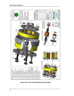
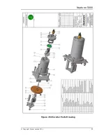
Page 52: ...Technical Manual 52 Figure 24 Inverter Pod Assembly ...
Page 55: ...Neptune 5000 Copyright Datem Limited 2014 55 Figure 25 Inverter Pod Wiring Schematic ...
Page 57: ...Neptune 5000 Copyright Datem Limited 2014 57 Figure 26 Inverter Function Settings ...
Page 62: ...Technical Manual 62 Figure 27 Thruster General Assembly ...
Page 63: ...Neptune 5000 Copyright Datem Limited 2014 63 Figure 28 Thruster Backplate and Driver Assembly ...
Page 64: ...Technical Manual 64 Figure 29 Thruster Drum and Cassette Assembly ...
Page 68: ...Technical Manual 68 ...
Page 70: ...Technical Manual 70 Figure 30 Thruster Straightener Assembly ...
Page 77: ...Neptune 5000 Copyright Datem Limited 2014 77 Figure 34 5cm2 Digital Cone Assembly ...
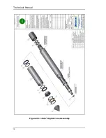
Page 78: ...Technical Manual 78 Figure 35 10cm2 Digital Cone Assembly ...
Page 90: ...Technical Manual 90 ...
Page 91: ...Neptune 5000 Copyright Datem Limited 2014 91 Figure 45 Encoder Parts Drawing ...
Page 95: ...Neptune 5000 Copyright Datem Limited 2014 95 ...
Page 102: ...Technical Manual 102 ...
Page 104: ...Technical Manual 104 ...
Page 105: ...Neptune 5000 Copyright Datem Limited 2014 105 ...
Page 106: ...Technical Manual 106 ...
Page 107: ...Neptune 5000 Copyright Datem Limited 2014 107 ...
Page 108: ...Technical Manual 108 ...
Page 110: ...Technical Manual 110 ...
Page 111: ...Neptune 5000 Copyright Datem Limited 2014 111 ...
Page 112: ...Technical Manual 112 ...
Page 113: ...Neptune 5000 Copyright Datem Limited 2014 113 ...
Page 115: ...Neptune 5000 Copyright Datem Limited 2014 115 ...
Page 116: ...Technical Manual 116 ...
Page 117: ...Neptune 5000 Copyright Datem Limited 2014 117 ...

