Technical Manual
24
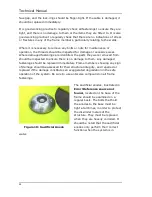
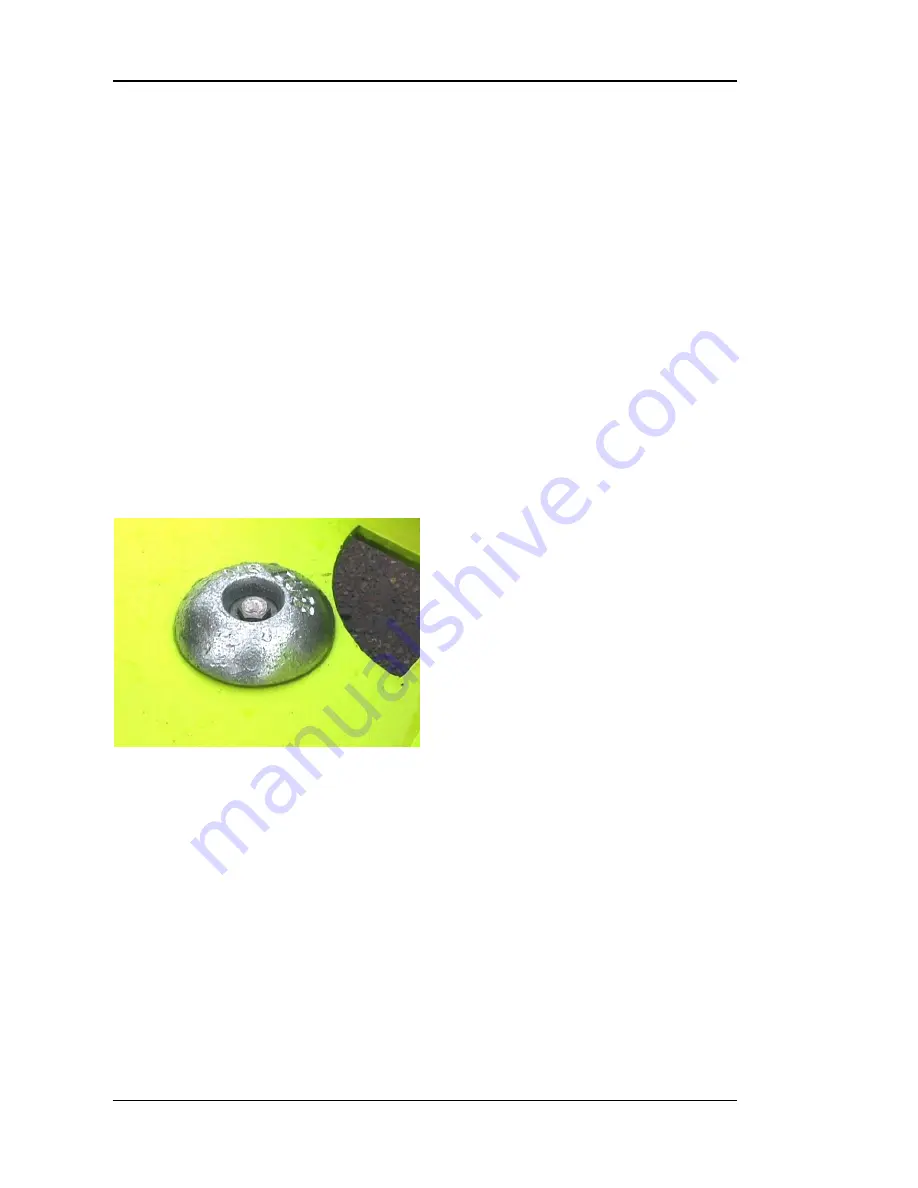
Figure 10: Sacrificial Anode
face gap, and the lock-rings should be finger-tight. If the cable is damaged, it
should be replaced immediately.
It is good working practice to regularly check all fastenings to ensure they are
tight, and there is no damage to them or the items they are fitted to. It is also
good working practice to regularly check that there are no indications of stress
or fractures in any of the frame members, particularly relating to the welds.
Where it is necessary to remove any bolts or nuts for maintenance or
operation, the threads should be inspected for damage or excessive wear.
Where damaged fastenings are identified, the parts they were removed from
should be inspected to ensure there is no damage to them. Any damaged
fastenings should be replaced immediately. Frame members showing any sign
of damage should be assessed for their structural integrity, and repaired or
replaced if the damage constitutes an exaggerated degradation in the safe
operation of the system. Be sure to use anti-seize compound on all frame
fastenings.
The sacrificial anodes, illustrated in
Error! Reference source not
found.
, located on the base of the
frame should be examined on a
regular basis. The bolts that hold
the anodes to the base must be
tight at all times, in order to protect
the dissimilar metals of the
structure. They must be replaced
when they are heavily corroded. It
should be noted that the sacrificial
anodes only perform their correct
function when the system is in
water.
Summary of Contents for Neptune 5000
Page 1: ...Neptune 5000 Copyright Datem Limited 2014 1 Neptune 5000 Technical Manual ...
Page 14: ...Technical Manual 14 Figure 3 Topside Control Box Wiring Schematic ...
Page 15: ...Neptune 5000 Copyright Datem Limited 2014 15 Figure 4 Topside Control Box Wiring Layout ...
Page 30: ...Technical Manual 30 ...
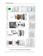
Page 32: ...Technical Manual 32 Figure 14 Transformer Pod General Arrangement ...
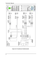
Page 36: ...Technical Manual 36 Figure 15 Transformer Pod Schematic ...
Page 39: ...Neptune 5000 Copyright Datem Limited 2014 39 Figure 16 Electronics Pod General Arrangement ...
Page 44: ...Technical Manual 44 Figure 19 Neptune 5000 Electronics Pod Wiring Schematic ...
Page 51: ...Neptune 5000 Copyright Datem Limited 2014 51 Figure 23 Inverter Pod General Arrangement ...
Page 52: ...Technical Manual 52 Figure 24 Inverter Pod Assembly ...
Page 55: ...Neptune 5000 Copyright Datem Limited 2014 55 Figure 25 Inverter Pod Wiring Schematic ...
Page 57: ...Neptune 5000 Copyright Datem Limited 2014 57 Figure 26 Inverter Function Settings ...
Page 62: ...Technical Manual 62 Figure 27 Thruster General Assembly ...
Page 63: ...Neptune 5000 Copyright Datem Limited 2014 63 Figure 28 Thruster Backplate and Driver Assembly ...
Page 64: ...Technical Manual 64 Figure 29 Thruster Drum and Cassette Assembly ...
Page 68: ...Technical Manual 68 ...
Page 70: ...Technical Manual 70 Figure 30 Thruster Straightener Assembly ...
Page 77: ...Neptune 5000 Copyright Datem Limited 2014 77 Figure 34 5cm2 Digital Cone Assembly ...
Page 78: ...Technical Manual 78 Figure 35 10cm2 Digital Cone Assembly ...
Page 90: ...Technical Manual 90 ...
Page 91: ...Neptune 5000 Copyright Datem Limited 2014 91 Figure 45 Encoder Parts Drawing ...
Page 95: ...Neptune 5000 Copyright Datem Limited 2014 95 ...
Page 102: ...Technical Manual 102 ...
Page 104: ...Technical Manual 104 ...
Page 105: ...Neptune 5000 Copyright Datem Limited 2014 105 ...
Page 106: ...Technical Manual 106 ...
Page 107: ...Neptune 5000 Copyright Datem Limited 2014 107 ...
Page 108: ...Technical Manual 108 ...
Page 110: ...Technical Manual 110 ...
Page 111: ...Neptune 5000 Copyright Datem Limited 2014 111 ...
Page 112: ...Technical Manual 112 ...
Page 113: ...Neptune 5000 Copyright Datem Limited 2014 113 ...
Page 115: ...Neptune 5000 Copyright Datem Limited 2014 115 ...
Page 116: ...Technical Manual 116 ...
Page 117: ...Neptune 5000 Copyright Datem Limited 2014 117 ...


