Neptune 5000
© Copyright Datem Limited 2014
49
The electrical cables connected to the Electronics Pod should be visually
inspected to ensure there are no chafes or cut in the insulation. The
connectors on both ends of the cables should be tightly fitted with no face gap,
and the lock-rings should be finger-tight. Any damaged cables or lock-rings
should be
Any signs of impact damage identified on the pod during visual inspection
should be investigated further, to ensure it has not compromised the integrity
of the pressure vessel. Any serious damage can result in the ingress of water,
and sub-sequential catastrophic failure.
Inverter Pod Assembly
Description
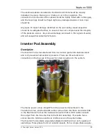
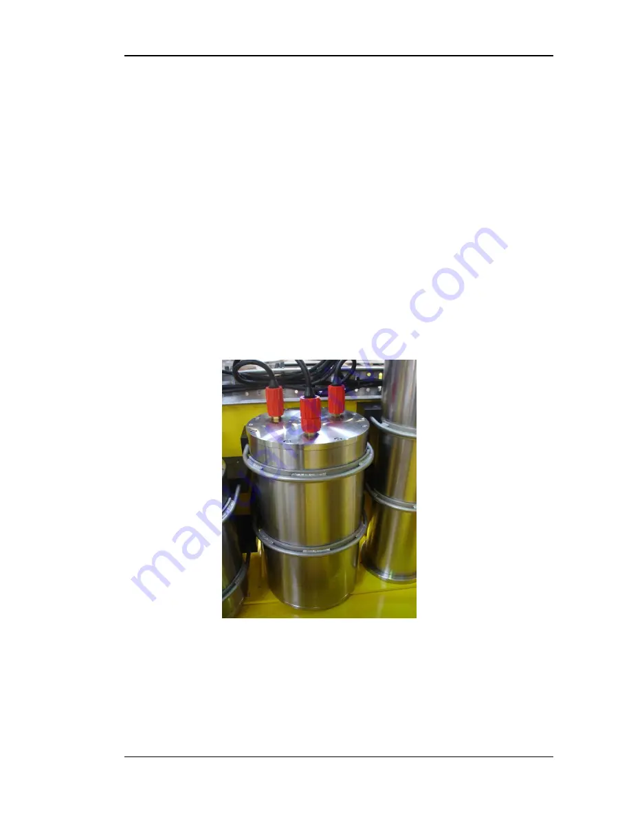
The Inverter Pod is manufactured from low carbon grade 316 stainless steel
and is dry sealed at atmospheric pressure. There are three Subconn
connectors on the top cap of the pod for interconnection to the system.
The mains power comes straight from the power terminal block in the
Transformer Pod, and the RS485 control comes from the Micro Controller PCB
in the Electronics Pod via the Subsea Connector PCB. A third cable connects
the output from the Inverter Pod to the Motor Assembly. This cable has a
screen braid to minimise electronic interference on the system data.
The Inverter Pod contains a specially adapted industrial drive unit, capable of
operating a three-phase motor at variable speeds, from a single-phase supply.
Summary of Contents for Neptune 5000
Page 1: ...Neptune 5000 Copyright Datem Limited 2014 1 Neptune 5000 Technical Manual ...
Page 14: ...Technical Manual 14 Figure 3 Topside Control Box Wiring Schematic ...
Page 15: ...Neptune 5000 Copyright Datem Limited 2014 15 Figure 4 Topside Control Box Wiring Layout ...
Page 30: ...Technical Manual 30 ...
Page 32: ...Technical Manual 32 Figure 14 Transformer Pod General Arrangement ...
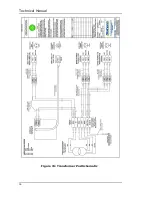
Page 36: ...Technical Manual 36 Figure 15 Transformer Pod Schematic ...
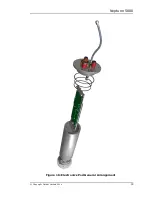
Page 39: ...Neptune 5000 Copyright Datem Limited 2014 39 Figure 16 Electronics Pod General Arrangement ...
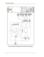
Page 44: ...Technical Manual 44 Figure 19 Neptune 5000 Electronics Pod Wiring Schematic ...
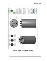
Page 51: ...Neptune 5000 Copyright Datem Limited 2014 51 Figure 23 Inverter Pod General Arrangement ...
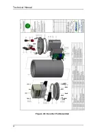
Page 52: ...Technical Manual 52 Figure 24 Inverter Pod Assembly ...
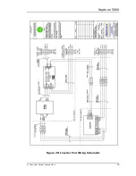
Page 55: ...Neptune 5000 Copyright Datem Limited 2014 55 Figure 25 Inverter Pod Wiring Schematic ...
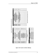
Page 57: ...Neptune 5000 Copyright Datem Limited 2014 57 Figure 26 Inverter Function Settings ...
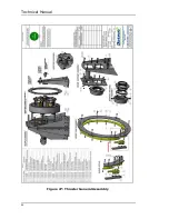
Page 62: ...Technical Manual 62 Figure 27 Thruster General Assembly ...
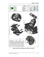
Page 63: ...Neptune 5000 Copyright Datem Limited 2014 63 Figure 28 Thruster Backplate and Driver Assembly ...
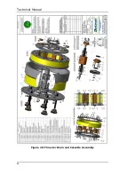
Page 64: ...Technical Manual 64 Figure 29 Thruster Drum and Cassette Assembly ...
Page 68: ...Technical Manual 68 ...
Page 70: ...Technical Manual 70 Figure 30 Thruster Straightener Assembly ...
Page 77: ...Neptune 5000 Copyright Datem Limited 2014 77 Figure 34 5cm2 Digital Cone Assembly ...
Page 78: ...Technical Manual 78 Figure 35 10cm2 Digital Cone Assembly ...
Page 90: ...Technical Manual 90 ...
Page 91: ...Neptune 5000 Copyright Datem Limited 2014 91 Figure 45 Encoder Parts Drawing ...
Page 95: ...Neptune 5000 Copyright Datem Limited 2014 95 ...
Page 102: ...Technical Manual 102 ...
Page 104: ...Technical Manual 104 ...
Page 105: ...Neptune 5000 Copyright Datem Limited 2014 105 ...
Page 106: ...Technical Manual 106 ...
Page 107: ...Neptune 5000 Copyright Datem Limited 2014 107 ...
Page 108: ...Technical Manual 108 ...
Page 110: ...Technical Manual 110 ...
Page 111: ...Neptune 5000 Copyright Datem Limited 2014 111 ...
Page 112: ...Technical Manual 112 ...
Page 113: ...Neptune 5000 Copyright Datem Limited 2014 113 ...
Page 115: ...Neptune 5000 Copyright Datem Limited 2014 115 ...
Page 116: ...Technical Manual 116 ...
Page 117: ...Neptune 5000 Copyright Datem Limited 2014 117 ...

