Datecs EP-2000 User Manual Download Page 16

Setup 


16 

DATECS

 ЕP-2000 

Memory Switches Setup 

EP-2000 has 13 memory switches, which have the following action:  

Flag 

OFF 

ON 

Power ON/OFF sound disabled 

Power ON/OFF sound enabled 

CR

 (ASCII code 13) is not executed 

CR

 is executed 

LF 

(ASCII code 10) 

LF

 (ASCII code 10) is executed 

LF

 (ASCII code 10) is not executed 

LF 

immediately after 

CR


as selected by flag 3 

LF 

immediately after 

CR  

is not executed 

Default is 

Font A

 (12x24) 

Default is

 Font B

 (9x16) 

Wide paper (78 mm) 

Thinner paper (58 mm) 

Не се използва 

Hardware flow control 

Xon/Xoff flow control 

USB interface disabled 

USB interface enabled 

10 

USB is ALWAYS in DEVICE mode 

11 

Normal operation mode 

Protocol mode 

12 

Cutter enabled 

Cutter disabled 

13 

Default select printer 

Default select customer display 

To change the settings: 

  1.


Изключете принтера. 

2.

 Switch 

ON

 the printer pressing 

FEED

 button.  


POWER – green, ERROR – red, 

are


rotated after every beep.  


3.

 After the  

4-th beep

 (after about 

6

 сек.) and 2 short  beeps,  


accompanied by 2 LED blinking  – 

POWER – green, ERROR – red.


After releasing the 

FEED

 button in this printer state,  


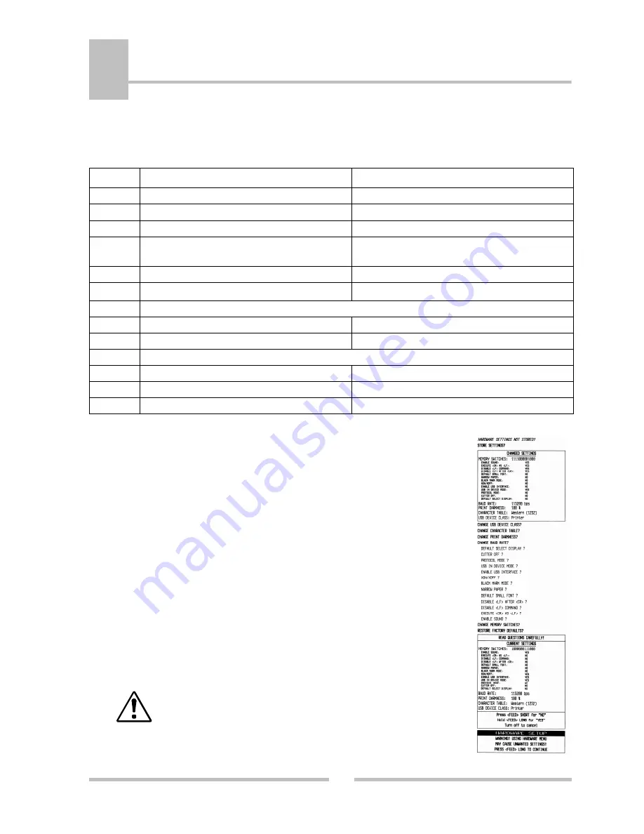
the printer enters the hardware setup mode (hardware menu)  


and prints the current settings.  


4.

 Follow the printer instruction  

to make the necesary changes. 


Care must be taken when 
changing factory preset 
configuration information. 

Long pressing the 

FEED

 button 

(YES)

 – confirms changes. 

Short pressing the 

FEED

 button 

(No Changes)

 – cancels changes. 

Summary of Contents for EP-2000

Page 1: ...DATECS USER S MANUAL ESC POS Thermal Printer EP 2000...

Page 2: ...ghts reserved Any mechanical electrical or electronic reproduction or adaptation of the information in this document without prior written permission from DATECS Ltd is prohibited 1784 Sofia Bulgaria...

Page 3: ...nal views and dimentions 10 Front view rear view 10 Printer inside 11 Operation panel 12 ON OFF switch and FEED button 12 LEDS 13 5 Setup Installing the printer 14 Printer Configuration 15 Memory Swit...

Page 4: ...kly and easily print text and or graphics depending on customer s needs barcodes logo etc Features Compact easy to use universal design High speed 220 mm s printing Low noise Easy paper loading Can be...

Page 5: ...System Step Printing Speed Max 220 mm s 1760 dots s Resident Fonts Font 12 24 dots 48 char line Font B 9 16 dots 64 char line Loadable Font C 12 24 dots 48 char line Font D 9 16 dots 64 char line Pap...

Page 6: ...tch ON OFF Paper feed Self test Dump Mode Switch On Switch OFF Power Switch ON OFF Weight Without paper 2 kg Dimensions mm 147 W X 207 D 147 H Environment Operating temperature conditions Storage temp...

Page 7: ...or spray insecticide on the printer If drink or water is spilled first be sure to turn the power off and then consult our service personnel When cleaning the surface of the printer case do not use the...

Page 8: ...optional products and consumable supplies other than the designated products contained herein Do not handle disassemble or repair the parts other than those specified in this manual DATECS is not lia...

Page 9: ...0 Thermal printer 2 AC power cord 3 RS232 Interface cable 4 1 Test Roll of thermal paper 5 User s Manual 6 EP 2000 Drivers 7 Partition for 58 60 mm paper rolls Because of the continually evolving Driv...

Page 10: ...rt Names and Functions 10 4 DATECS P 2000 External view and dimentions Front view rear view ON OFF power switch Operation panel Printer cover Cover open button Connectors 1 2 4 3 5 Front view Rear vie...

Page 11: ...11 DATECS P 2000 Printer inside Printing thermal head Auto cutter Paper near end sensor Paper end sensor Paper feed roller Connectors 1 LAN 2 RS232 3 Display 4 USB 5 Drawer 1 2 4 3 5 2 1 3 4 5...

Page 12: ...s the type of error ON OFF switch and FEED button functions Functions ON OFF 1 Switch ON Switch OFF the printer 1 Pressing LF button feeding the media while the button is pressed after releasing the b...

Page 13: ...OWER flashes green and the printer continues to print 4 When switching ON the printer while the FEED button is pressed POWER Green ERROR red flashes are rotated after every beep up to the fifth Depend...

Page 14: ...2000 Installing the printer The printer must be operated horizontally only Do not operate vertically or install on a wall Connecting the AC power cord Interfaces AC inlet AC power cord RS 232 USB LAN...

Page 15: ...green ERROR red are rotated after every beep 3 After the 4 th beep after about 6 and 2 short beeps accompanied by 2 LED blinking POWER green ERROR red After releasing the FEED button in this printer...

Page 16: ...d 10 USB is ALWAYS in DEVICE mode 11 Normal operation mode Protocol mode 12 Cutter enabled Cutter disabled 13 Default select printer Default select customer display To change the settings 1 2 Switch O...

Page 17: ...of the roll paper used Sensor position Roll paper diameter at the detection of near end mm Outer core diameter of roll paper used 1 22 18 2 25 22 3 29 25 4 34 32 Loading Drivers for P 2000 To print in...

Page 18: ...roll The thermal roll must be placed as shown in the figure on the right the thermal surface of the media must be faced to the thermal head 4 Close theprinter cover until aclick can be heard Be sure...

Page 19: ...t SELF TEST Press and Hold the LF button while Power On the printer Release after 0 5 sec and after the 1 beep The printer will print a Short Self Test which contains information about priter cofigura...

Page 20: ...rinter Release after 4 5 sec and after the 3 beep The printer will print a Long Self Test which contains additional information about Rezident font sizes Characters per line Text formating Rezident ch...

Page 21: ...See section Loading Paper for details on replacing paper cover 2 POWER Green ERROR red are rotated The printer thermal head is overheat When the printer head temperature returns to normal the POWER f...

Page 22: ...ffer 13 DC3 D Ruled line pattern set 14 DC3 F Ruled line line set 15 DC3 L Selects ruled line combine mode 16 DC3 M Ruled line 1 dot line print 17 DC3 P Ruled line n dots line print 18 DC3 p Ruled lin...

Page 23: ...Selecting country 47 ESC S Specifying speed bps of the serial port 48 ESC T Printing short self test 49 ESC U Selecting Canceling underlined printing 50 ESC V Selecting Canceling printing 90 right tur...

Page 24: ...Downloaded Bit Image 79 GS Starting ending macro definitions 80 GS B Enabling Disabling inverse printing white on black 81 GS C Read the Real Time Clock 82 GS H Selecting Printing position of HRI Code...

Page 25: ...S Specifying printing mode of two byte text data 104 FS Selecting two byte text mode JIS or GB2312 105 FS Selecting Canceling underline mode for two byte text mode 106 FS Canceling two byte text mode...

Reviews: