background image


11 

5.


PI

P E

ffe

ct


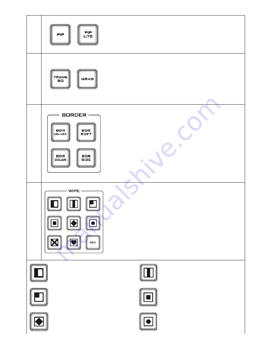
PIP

 enables the PIP key mode 


PIP LITE

 enables the PIP LITE key mode 


6.


Ba

ck

gr

ou

nd


Tr

an

sit

io

n &

 G

RAB


TRANS BG

 enables Background Transition between Program / 

Preset 

GRAB 

grabs the current Program video image 

7.


W

ip

Bo

rd

er

 S

et

tin


BDR ON/OFF

 turns the WIPE border function ON/OFF 


BDR SOFT

 configures the WIPE border softness 


BDR COLOR

 selects the WIPE border color 


BDR SIZE

 adjusts the WIPE border thickness 

8.


W

ip

Tr

an

sit

io

n S

ele

ct

io


WIPE Transition Selection 

The HS-1200 has 8 user defined wipe buttons that allow the user 

to select WIPE transition effect directly from the control panel. 

The REV button reverses the direction of the selected WIPE. 


All wipes can have an optional colour border applied. The wipe 

border width and colour are chosen within the menu system. 


Transitions can be performed manually using the T-Bar or 

automatically by using the SPEED and AUTO TAKE buttons. 


Vertical Wipe Left to Right 


Vertical Wipes from Centre to Left and 

Right sides


Upper Left corner Wipe to Lower 

Right corner 


Box Wipe from Centre to outside 

edges


Diamond Wipe from Centre to outside 

edges 


Circle Wipe from Centre to outside 

edges


Summary of Contents for HS-1200

Page 1: ......

Page 2: ...ONTROL PANEL 9 3 2 MONITOR CONTROL PANEL 14 4 SWITCHER OSD MENU OVERVIEW 16 5 SWITCHER OSD MENU FUNCTIONS 22 5 1 START 22 Transition 22 Wipe Effects 22 Border 23 Position 23 Matte 23 5 2 KEYER 23 Keyer Control 23 Key Source 24 Fill Source 24 Mask 24 5 3 CHROMA 24 Keyer 24 CK Setup 25 Mask 25 5 4 P IN P 25 Position 26 Border 26 Border Width 26 Crop 26 5 5 P IN P LITE 26 Position 27 Border 27 Border...

Page 3: ...s intended as a guide only At all times Datavideo Technologies will try to give correct complete and suitable information However Datavideo Technologies cannot exclude that some information in this manual from time to time may not be correct or may be incomplete This manual may contain typing errors omissions or incorrect information Datavideo Technologies always recommend that you double check th...

Page 4: ...hat the total of the ampere ratings on the products plugged into the extension cord do not exceed the extension cord s rating 10 Make sure that the total amperes of all the units that are plugged into a single wall outlet do not exceed 15 amperes 11 Never push objects of any kind into this unit through the cabinet ventilation slots as they may touch dangerous voltage points or short out parts that...

Page 5: ...r a free one year extension to the standard Warranty providing the product is registered with Datavideo within 30 days of purchase For information on how to register please visit www datavideo tek com or contact your local Datavideo office or authorized Distributors Certain parts with limited lifetime expectancy such as LCD Panels DVD Drives Hard Drives are only covered for the first 10 000 hours ...

Page 6: ...great value solution for the worship education and AV market 1 1 Features 6 video inputs SDI x 4 HDMI x 2 Frame Sync on each input 2 Video Output SDI x 1 HDMI x 1 4 x XLR Analogue Audio Inputs Flexible Mix Effects Processor with 2 Upstream Keyers supporting Chroma Key Linear Luma Key 2 DSK supporting Linear Luma Key Modes 1 PIP assignable to any of the 4 keyers Wipe Generator 32 Wipe Patterns incl...

Page 7: ...nector 6 HD SDI Video Input 3 4 13 Tally Connector 7 HD SDI Video Output 2 1 Rear Panel Connections Ethernet Port Remote control interface RS 232 Remote Remote control interface Tally Sends Red and Green tally signals to each channel Red indicates On Air and Green indicates next camera source GPI The GPI socket can be used for simple external control Note Please configure GPI settings in the Switc...

Page 8: ...2V 5A PSU to this 4 PIN XLR socket SDI Video Output The BNC output connector is a user defined SDI output Note Please set the OUTPUT SOURCE in the Switcher Menu HDMI Video Ouput The HDMI output connector is a user defined HDMI output Note Please set the OUTPUT SOURCE in the Switcher Menu Video Input Modules The HS 1200 is equipped with six video input channels Video Input set is comprised of four ...

Page 9: ...reviously saved switcher settings SHIFT There are 12 user memory locations Under normal circumstances Buttons USER 1 to 6 represent user memory locations 1 to 6 To load settings saved in locations 7 to 12 to buttons USER 1 6 simply press the SHIFT button SAVE User Memory Save The SAVE button saves the current switcher settings To save keep holding down this button and then select the User Memory n...

Page 10: ... enables key 1 on the Multi view and PVW output Key 2 PVW enables key 2 on the Multi view and PVW output DSK 1 PVW enable DSK 1 on the Multi view and PVW output DSK 2 PVW enable DSK 2 on the Multi view and PVW output 4 Keyer Source Selection of Keyer Source from Program Preset Row Keep holding down one of these buttons to enter key select mode and fill select mode Select key source from the Progra...

Page 11: ...ion The HS 1200 has 8 user defined wipe buttons that allow the user to select WIPE transition effect directly from the control panel The REV button reverses the direction of the selected WIPE All wipes can have an optional colour border applied The wipe border width and colour are chosen within the menu system Transitions can be performed manually using the T Bar or automatically by using the SPEE...

Page 12: ...using any of the transition controls Buttons 1 2 3 4 5 and 6 are video source buttons BLK Black background the black background for use on the Program and Preset row BG Background button assigns a background colour or colour bars for use on the Program and Preset row 10 Transition Effect FTB Fade To Black this button fades the current video program source to black When pressed again it acts in rev...

Page 13: ...rforms a simple immediate switch from the current main source to the selected sub source The selected transition wipe or MIX is not used AUTO TAKE This performs an automated switch from the current program source to the selected Preview source The selected transition wipe or MIX will also be used The timing of the transition is set by the chosen Speed button 11 Audio Control Headphone Socket 6 3mm...

Page 14: ...he screen This allows adjustments of chroma and phase Phase adjustment is effective with NTSC signals PTN When pressed displays internally generated SMPTE 75 Colour Bars Press again to return to the previously selected video input ZOOM This feature is designed for use with HD SDI and HDMI sources above 720p resolution Press this button to zoom in to the video on the display This is strictly a zoom...

Page 15: ...gate the set up menus See Monitor Menu Options for more details Aspect Ratio Button Sets the Aspect Ratio to 16 9 4 3 Volume Control Adjusts the speaker headphone volume up down MUTE Mutes the audio from the internal speakers or headphone socket ...

Page 16: ...fects Wipe Wipe Effect Presets Soft Border Softness Width Border Width Border Luma Border Color Luma Sat Border Color Saturation Hue Border Color Hue Position X Horizontal Position Y Vertical Position Matte Luma Background Matte Luma Sat Background Matte Saturation Hue Background Matte Hue Keyer Keyer DSK 2 DSK 1 Key 2 Key 1 Keyer Selection Keyer Ctrl Chroma Luma Linear Type of Keyer P in P Lite P...

Page 17: ...current Keyer source Hue Parameter for color of the chroma key Luma Parameter for luma of the chroma key K Range Setting the range of colors that match the background color to be keyed K Fgnd Adjusts the performance of the chroma key in dark or black areas K Bgnd Adjusts the performance of the chroma key in light or white areas Hi Light Boosts the foreground key in high luminance area Lo Light Boo...

Page 18: ...Width PIP Border Width Crop Left Left Edge of the Crop Right Right Edge of the Crop Size Size of the Crop Top Top Edge of the Crop Bot Bottom Edge of the Crop Inputs Input 1 Black Black Level White White Level Chrom Chroma Level Input 2 Black Black Level White White Level Chrom Chroma Level Input 3 Black Black Level White White Level Chrom Chroma Level Input 4 Black Black Level White White Level C...

Page 19: ...ut 2 Input 1 OFF 4 Input 6 Input 5 Input 4 Input 3 Input 2 Input 1 OFF 5 Input 6 Input 5 Input 4 Input 3 Input 2 Input 1 OFF 6 Input 6 Input 5 Input 4 Input 3 Input 2 Input 1 OFF Outputs Output SDI1 SDI2 HDMI Input 6 Input 5 Input 4 Input 3 Input 2 Input 1 CLN PVW Clean PVW CLN PGM Clean PGM PG DSK PVW PGM MultiV Multi view HDMI Output Resolution 1080i 1080p ...

Page 20: ...ure 1 Preview of the previous image Thumbnail Picture Preview of the image to be loaded Thumbnail Picture 1 Preview of the next image Save Still Save Pressing this button saves the selected still picture Source Input6 Input5 Input4 Input3 Input2 Input1 Still Memory Location 0 500 Freeze 1 Sets the Frame store mode of Input 1 to Clip Still Freeze Live 2 Sets the Frame store mode of Input 2 to Clip ...

Page 21: ...ion Auto Save ON OFF Automatically saves the last settings before the machine is shut down once turned ON auto save also occurs upon every Still Load Factory Def Reset Factory Default Reset loads the default configuration from memory point 0 for all configuration options except for the Setup Reset Names Resets the Multiviewer labels to the default settings Language English Traditional Chinese Simp...

Page 22: ...e below Advanced Mode Start Transition M E 60 DSK 60 FTB 60 Keyer Type Wipe Chroma P in P Wipe Effects Wipe 1 Soft 0 Width 0 P in P Lite Border Luma 100 Sat 80 Hue 178 Inputs Position X 0 Y 0 Outputs Stills Matte Luma 100 Sat 80 Hue 0 User Mems Setup Basic Mode Start Transition M E 60 DSK 60 FTB 60 Keyer Chroma Wipe Effects Wipe 1 Soft 0 Width 0 P in P P in P Lite Inputs Outputs Stills User Mems S...

Page 23: ...Luma Saturation and Hue under this sub option 5 2 Keyer In this option the user is able to configure four keyers which are Key 1 Key 2 DSK 1 and DSK 2 Advanced Mode Basic Mode Start Keyer Key 1 Keyer Chroma Keyer Ctrl Chroma P in P Priority Bot P in P Lift 0 Gain 1 0 Opac 100 P in P Lite Key Source Input 1 Fill Input 3 Inputs Outputs Mask Left 0 Right 0 Stills Top 0 Bot 0 User Mems Setup Keyer Con...

Page 24: ...fill source if Split is selected various options are listed below Bars Matte Input6 Input5 Input4 Input3 Input2 Input1 Black Mask The Mask feature allows the user to configure the Mask in chroma luma or linear mode Left Left sets the left edge of the keyer mask Right Right sets the right edge of the keyer mask Top Top sets the top edge of the keyer mask Bottom Bottom sets the bottom edge of the ke...

Page 25: ...e value if the light areas are becoming too transparent Hi Light Hi light boosts the foreground key in high luminance area Lo Light Lo light boosts the foreground key in low luminance area Bg Supp Background Suppress removes the Luma Brightness of the background from the final image Bg Supp turns ON OFF background suppression Mask The Mask feature allows the user to configure the Mask in chroma mo...

Page 26: ...order width A width of zero 0 will turn the P in P window border off Crop The P in P window crop can be adjusted by modifying the following parameters Left Adjusts the position of the left edge of the P in P window Right Adjusts the position of the right edge of the P in P window Size Adjusts the P in P window crop size Top Adjusts the position of the top edge of the P in P window Bot Adjusts the ...

Page 27: ... P in P window Size Adjusts the P in P window crop size Top Adjusts the position of the top edge of the P in P window Bot Adjusts the position of the bottom edge of the P in P window 5 6 Inputs This feature allows the user to configure the color of the Inputs 1 4 In addition the user can shuffle the contents between Inputs 1 6 or turn off the input channel Advanced Mode Start Input 1 Black 0 White...

Page 28: ...e sources of Inputs 1 6 to the 6 input buttons 1 2 3 4 5 and 6 of the Program and Preset rows as desired 5 7 Outputs This option allows the user to configure various output settings such as video output audio output and GPI Out Advanced Mode Start Output Sdi 1 Pgm Sdi 2 Input 2 HDMI MultiV Keyer HDMI 1080P Chroma Audio Mode On Level Auto P in P Sdi 1 On Sdi 2 On HDMI On P in P Lite Inputs GPI Out ...

Page 29: ...00 or AD 200 could be considered By changing the Audio sub option from ON to OFF will mute the incoming XLR audio from the external master audio mixer Level EBU SMPTE AUTO There are two different audio standards available for selection The user can either select the EBU or SMPTE standard By selecting AUTO allows the device to automatically detect the audio standard GPI Out This allows the user to ...

Page 30: ...puts Stills User Mems Setup Load Still Upon selecting Load Still the user can then choose the memory location from which the still image is loaded The following are the destinations to which the still image can be loaded Input 6 Input 5 Input 4 Input 3 Input 2 Input 1 Select Load to load the still image to the determined destination Image Preview is available below the Load Still row Image Preview...

Page 31: ...ed setting by selecting Load The user can also press one of the USER memory shortcut buttons 1 6 on the control panel as a quick way of loading those previously saved User configurations Save Memory Use the up down arrow to scroll to the desired memory location and save the current setting by selecting Save 5 10 Setup In the Setup menu the user can change the resolution switch between full and sim...

Page 32: ...s option allows the user to choose the appropriate output resolution such as 1080i 50 Once done simply select Save Setup to confirm the selected output resolution The available resolutions are 1080i 50 59 94 60 720p 60 59 94 50 Menu Mode The user is allowed to switch between full and simplified menu versions Select Advanced for full menu display or Basic to display a simplified version of the OSD ...

Page 33: ...This option is only available when the USB storage device containing the latest firmware file is inserted Select Upgrade to start the firmware upgrade process Refer to the FIRMWARE UPDATE section for more details At the bottom of the menu you will be able to view the version number of the latest firmware installed ...

Page 34: ...d within the switcher s non volatile memory Main Options Sub Options Parameters Parameters MAIN ADJUST BRIGHTNESS 0 100 CONTRAST 0 100 SHARPNESS 0 100 SATURATION 0 100 TINT 0 100 BACK LIGHT 0 100 NR HIGH MID LOW OFF MPEG NR HIGH LOW OFF VOLUME 0 100 EXIT COLOR 6500 9300 7500 USER COLOR RED 0 100 GREEN 0 100 BLUE 0 100 EXIT SCAN SETTING UNDER SCAN full image OVER SCAN cropped image INFORMATION H FR...

Page 35: ...as this could result in a non responsive unit 1 Locate the FW Upgrade USB port on the front panel of the HS 1200 2 Insert the USB stick that contains the latest firmware to the FW upgrade port 3 Power on the device and the device should automatically detect the connected USB storage device 4 Press the MENU button on the control panel to open the menu on the monitor screen 5 Press the down arrow bu...

Page 36: ...lly output port These connections provide bi colour tally information to a number of other Datavideo products such as the ITC 100 eight channel talkback system and the TLM range of LCD Monitors The ports are open collector ports and as such do not provide power to tally light circuits The pin outputs are defined as follows PIN No Signal Name Input Output Description of Signal 1 Program 1 Open coll...

Page 37: ...37 10 Dimensions All measurements in millimetres mm ...

Page 38: ...nput 1 6 Audio Indicator on Multi view Y output 2CH Computer Output Ethernet Motion JPEG Out Control Panel Connection RS 232 Tally Out Y GPI Two mode Level Pulse trigger selectable Speaker Volume Control Control Knob Software Updates Ethernet Monitor LCD Display 17 3 TFT LCD Resolution RGB 1600 x 900 pixel Aspect Ratio 4 3 and 16 9 selectable LED Life time 12 000 hrs approx Brightness Luminance 22...

Page 39: ...ontrol HD Down Conversion N A Extras Upstream Keyers 2 M E Keyer PIP Downstream Keyers 2 Linear Luma Keyers 4 Chroma Keyers 2 M E Keyer PIP Pattern Generators Color Bar PIP 1 XPT Y Frame store Any Input can be used as Frame store 8 Still frames stored in local frame buffers for instant access Control Panel Compatibility Use PC via Ethernet Control Panel Input Voltage 8V 17V Multi View Monitoring N...

Page 40: ...40 Service and Support ...

Reviews: