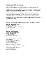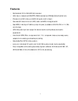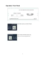
6
Installation
Connection:
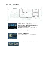
1 DV In/Out
Connect a DV source to one of the DV connectors at the rear of the DAC-5 for input and
output. Source must comply with IEEE-1394 (i.Link) standard. Two 6-pin DV connectors
effectively provide active loop-through when the unit is turned on.
2 SDI In/Out
Connect an SDI signal to the SDI input BNC connector (left-hand side) labeled SDI. The
DAC-5 accepts 4:2:2 serial digital video signals in either 525 or 625 line formats. The
input signal must conform to the SMPTE 259M standard. Connect destination equipment
to the SDI output BNC connector (right-hand side). The DVITC timecode in the output
signal respects the same standard as the one in the input signal.
3 AES In/Out
Connect an unbalanced AES signal to the AES input BNC connector labeled AES. The
DAC-5 supports 32, and 48 kHz sample rates. This signal must comply with the
AES-3id-1995 (SMPTE 276M) standard. Connect destination equipment to the AES
output BNC connector.
4 Monitoring Output
Connect analog destination equipment to the connectors at the rear of the DAC-5. Use
the BNC labeled Composite or the mini-Din labeled S-Video for video output; use the two
RCA labeled R and L for audio output.


