background image


- 10 - 

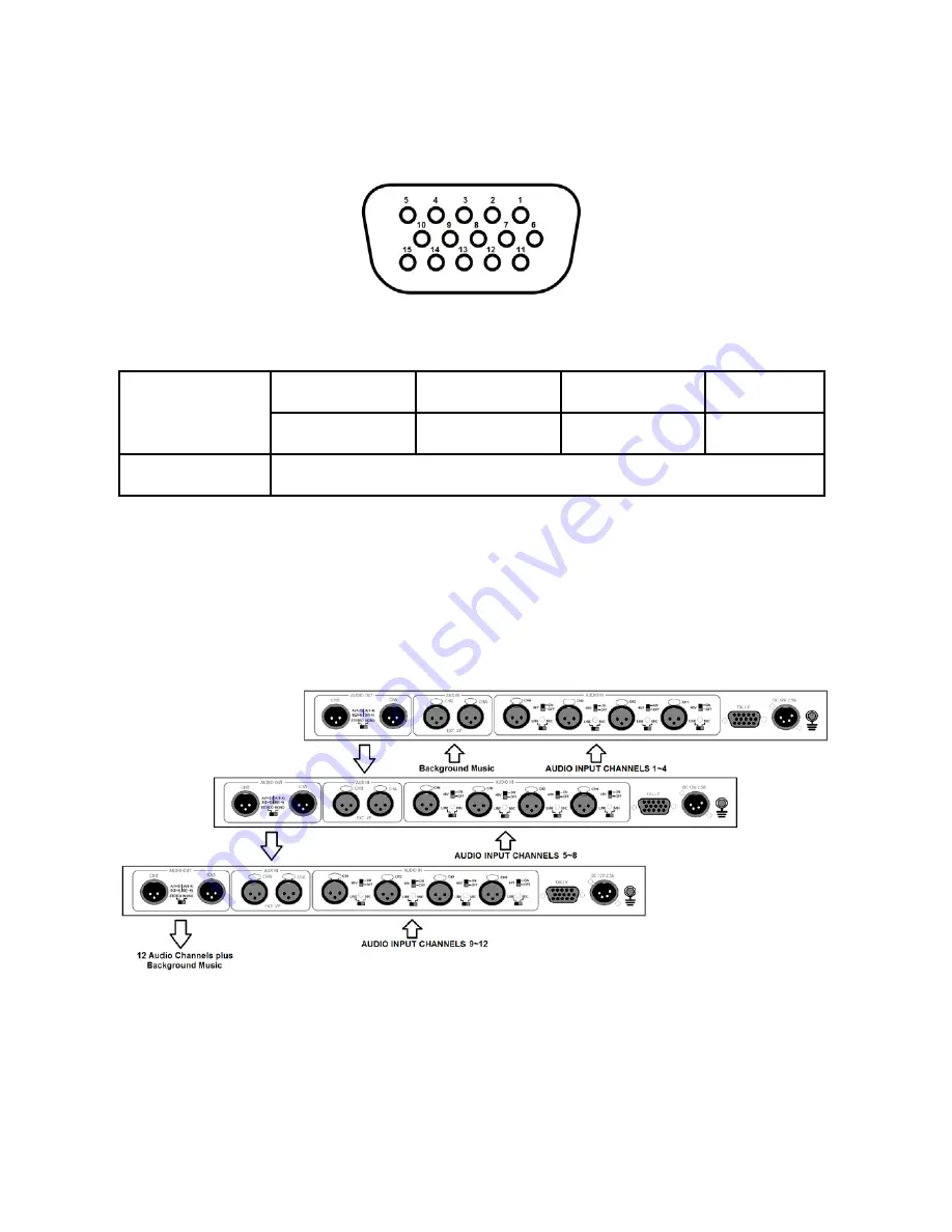
Tally Input Connector (A+V feature) 

The Tally output from a video mixer allows the AM-100 to automatically switch between audio 

sources with the video mix.  


D-Sub 15PIN Female 


PIN assignment of the Tally Connector is shown in the table below: 

Audio Channels 

CH 1 

CH 2 

CH 3 

CH 4 

Pin 1 

Pin 6 

Pin 11 

Pin 5 

GND 

Pins 4 / 9 / 14 


Example Cascade Setup 

It is possible to cascade or daisy chain several AM-100 units together. This allows more audio 

sources to be added to the set up and provided at the final mixed output.  To daisy chain units 

together take the AUDIO OUT pair from the first unit and connect these to the AUX IN on the 

second unit. Below diagram shows 3 units connected in this way. 


Summary of Contents for AM-100

Page 1: ...AM 100 AUDIO MIXER Instruction manual...

Page 2: ...correct complete and suitable information However Datavideo Technologies cannot exclude that some information in this manual from time to time may not be correct or may be incomplete This manual may...

Page 3: ...e this unit where the power cord will be walked on rolled over or otherwise stressed 9 If an extension cord must be used with this unit make sure that the total of the ampere ratings on the products p...

Page 4: ...not required by our computer systems are not covered under warranty All mail or transportation costs including insurance are at the expense of the owner All other claims of any nature are not covered...

Page 5: ...onserve natural resources and ensure that it is recycled in a manner that protects human health and the environment For more information about where you can drop off your waste equipment for recycling...

Page 6: ...cut filter on mic input channels High resolution 8 segment stereo meters Supports both Line or Microphone with 48v Phantom power Fifth auxiliary channel can be used as line or for daisy chaining with...

Page 7: ...ll be sent to the Audio Bus and its associated Fader This row of audio channel selection buttons has LEDs built in to show which input channel is active Level control for each audio input source is vi...

Page 8: ...the circuit The 48V ON OFF switch is for phantom power If you want to use MIC in please set the LINE MIC switch first and then if using a Condenser microphone turn ON the 48V ON OFF switch If you wish...

Page 9: ...ut channels will be applied to the Video bus at the Fader In fact you have to select one or more of these channels or there will be no audio present at the audio out connections The A V button should...

Page 10: ...Audio Channels CH 1 CH 2 CH 3 CH 4 Pin 1 Pin 6 Pin 11 Pin 5 GND Pins 4 9 14 Example Cascade Setup It is possible to cascade or daisy chain several AM 100 units together This allows more audio sources...

Page 11: ...20 1 5 dB AUX IN knob Signal to noise ratio 70 min dB 1KHz 0dB THD N 0 06 max 1KHz 0dB Frequency Response 20Hz 20KHz 3 dB Audio Output Parameter Specifications Limit Units Conditions Comments Connect...

Page 12: ...91 0120 2427338 E mail sales datavideo in Tel 91 0120 2427337 A 132 Sec 63 Noida 201307 India India Noida Datavideo India Kochi Tel 91 4844 025336 Fax 91 4844 047696 2nd Floor North Wing Govardhan Bui...

Reviews: