


CASCADE SYSTEM
86
SH4 BASE-STANDARD
PROTECTED AREA
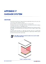
When installing a cascade system detection capability at the edge of each unit depends
on how cascade units are linked with each other. If the proper cascade brackets are used
detection capability at the edges can be calculated according to brackets documenta
-
tion. In both 30mm and 14mm resolution unit user can always achieve less then 40mm
resolution.
OPERATION
A proprietary transmission protocol is used to communicate both Slaves safety related
information and status info.
OSSDs are connected to (and thus controlled by) Master unit only.
The redundancy of information and a series of data integrity checks guarantee that
safety critical parameters are correctly transferred between cascade units. If that trans
-
mission fails due to a stuck at fault or a signal degradation both master and slaves unit
stops into Communication Failure Lockout.
A maximum of one master and two slave units (M+S
1
+S
2
) can be connected in a cas
-
cade.
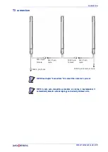
14mm and 30mm resolution can be mixed in a cascade system and as described in the
previous chapter,
cascade system must have the following topology:
Cascade Topology (units' number, length and resolution) is auto-detected at start-up
and stored in light curtain memory for safety reasons. If topology is changed, a Reset to
Factory Configuration must be performed for Standard Muting master models or a new
GUI parametrization for Advanced master models before the new cascade can be oper
-
ated.
UNIT
ALLOWED SH4 MODELS
MASTER
SH4-XX-XXXX-SM-8-5 Standard Muting
SH4-XX-XXXX-A-12-5 Advanced
MID SLAVE (optional)
SH4-XX-XXXX-C-5-5
LAST SLAVE
SH4-XX-XXXX-B-5
1
SH4-XX-XXXX-C-5-5 (for muting connection)
1. Only for Advanced models and depending on their configuration, it is possible to have muting
connections.
NOTE: Please refer to the dedicated Product Reference Guide for resetting
the Advanced or Standard Muting master models.
Summary of Contents for SH4 BASE-STANDARD
Page 1: ...SH4 BASE STANDARD PRODUCT REFERENCE GUIDE Safety Light Curtains...
Page 6: ...CONTENTS vi SH4 BASE STANDARD...
Page 13: ...COMPLIANCE PRODUCT REFERENCE GUIDE 5...
Page 29: ...GENERAL INFORMATION ON DEVICE POSITIONING PRODUCT REFERENCE GUIDE 21...
Page 33: ...PRODUCT REFERENCE GUIDE 25...
Page 38: ...ELECTRICAL CONNECTIONS 30 SH4 BASE STANDARD...
Page 59: ...SH4 X XXXX X X MODELS PRODUCT REFERENCE GUIDE 51...
Page 65: ...PRODUCT REFERENCE GUIDE 57...
Page 69: ...RESPONSE TIMES PRODUCT REFERENCE GUIDE 61...
Page 73: ...SH4 2 3 4 XXXX X X PRODUCT REFERENCE GUIDE 65...
Page 75: ...METAL ANGLED FIXING BRACKET PRODUCT REFERENCE GUIDE 67...