


FUNCTIONS
40
SH4 BASE-STANDARD
EDM
(Standard models only)
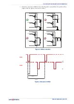
The External Device Monitoring (EDM) function controls external devices by verifying
the OSSDs status. To correctly use this function user must connect EDM input to a N.C.
to 24V contact of the device to control (forced guide relay).
Figure 8: EDM wiring
The function controls the N.C. contact switching according to the changes of the OSSD
status.
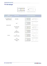
The timing diagram below explains the relationship between the cause (OSSDs) and the
effect (EDM), with the maximum permissible delay.
Figure 9: EDM function timing
T
c
350 ms (time between OSSD OFF-ON transition and EDM test)
T
0
100 ms (time between OSSD ON-OFF transition and EDM test)
(two different times for the mechanical contact driven by a spring)
Configuration
The configuration of EDM is done by connecting the EDM SEL signal (
pin 3
,
green
) as
described below:
• EDM SELECTION connected to 0V (floating): EDM ENABLED
• EMD SELECTION connected to 24V: EDM DISABLED
24Vdc
OSSD_1
OSSD_2
EDM
OSSD_1
OSSD_2
EDM
ESPE
ESPE
Safety MPCE
forced guide
relais
EDM ENABLED
EDM DISABLED
floating
nc
nc
no
no
ON
OFF
24Vdc
0Vdc
OSSDs
STATUS
EDM
Tc
To
Summary of Contents for SH4 BASE-STANDARD
Page 1: ...SH4 BASE STANDARD PRODUCT REFERENCE GUIDE Safety Light Curtains...
Page 6: ...CONTENTS vi SH4 BASE STANDARD...
Page 13: ...COMPLIANCE PRODUCT REFERENCE GUIDE 5...
Page 29: ...GENERAL INFORMATION ON DEVICE POSITIONING PRODUCT REFERENCE GUIDE 21...
Page 33: ...PRODUCT REFERENCE GUIDE 25...
Page 38: ...ELECTRICAL CONNECTIONS 30 SH4 BASE STANDARD...
Page 59: ...SH4 X XXXX X X MODELS PRODUCT REFERENCE GUIDE 51...
Page 65: ...PRODUCT REFERENCE GUIDE 57...
Page 69: ...RESPONSE TIMES PRODUCT REFERENCE GUIDE 61...
Page 73: ...SH4 2 3 4 XXXX X X PRODUCT REFERENCE GUIDE 65...
Page 75: ...METAL ANGLED FIXING BRACKET PRODUCT REFERENCE GUIDE 67...