


INSTALLATION
10
SH4 BASE-STANDARD
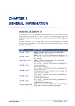
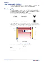
Minimum installation distance
The safety device must be positioned at a specific safety distance (Operating distance).
This distance must ensure that the dangerous area cannot be reached before the dan
-
gerous motion of the machine has been stopped by the Safety Control System.
The safety distance depends on 4 factors, according to the EN ISO 13855 Standard:
• Response time of the ESPE (the time between the effective beam interruption and
the opening of the OSSD contacts)
• Machine stopping time including Safety Control System computing and actuating
time if present.
• ESPE resolution
• Approaching speed of the object to be detected
Figure 3: Installation distance (vertical positioning)
The following formula is used for the calculation of the safety distance:
S = K (t1 + t2) + C
where:
• S = Minimum safety distance in mm
• K = Speed of the object, limb or body approaching the dangerous area in mm/s
• t1 = Response time of the ESPE in seconds (see appendix “Technical Data”.)
• t2 = Machine stopping time in seconds (including the Safety Control System)
• C = Additional distance based on the possibility to insert the body or one of the
body parts inside the dangerous area before the protective device trips.
• C = 8 (R - 14) for devices with resolution ≤ 40 mm
• C = 850 mm for devices with resolution > 40 mm
• R = Resolution of the system
When devices with > 40 mm resolution are used, the height of the top beam has to be ≥
900 mm (H2) from machine supporting base while the height of the bottom beam has
to be ≤ 300 mm (H1).
NOTE: K value is:
2000 mm/s if the calculated value of S is ≤ 500 mm
1600 mm/s if the calculated value of S is > 500 mm
Summary of Contents for SH4 BASE-STANDARD
Page 1: ...SH4 BASE STANDARD PRODUCT REFERENCE GUIDE Safety Light Curtains...
Page 6: ...CONTENTS vi SH4 BASE STANDARD...
Page 13: ...COMPLIANCE PRODUCT REFERENCE GUIDE 5...
Page 29: ...GENERAL INFORMATION ON DEVICE POSITIONING PRODUCT REFERENCE GUIDE 21...
Page 33: ...PRODUCT REFERENCE GUIDE 25...
Page 38: ...ELECTRICAL CONNECTIONS 30 SH4 BASE STANDARD...
Page 59: ...SH4 X XXXX X X MODELS PRODUCT REFERENCE GUIDE 51...
Page 65: ...PRODUCT REFERENCE GUIDE 57...
Page 69: ...RESPONSE TIMES PRODUCT REFERENCE GUIDE 61...
Page 73: ...SH4 2 3 4 XXXX X X PRODUCT REFERENCE GUIDE 65...
Page 75: ...METAL ANGLED FIXING BRACKET PRODUCT REFERENCE GUIDE 67...