background image

1-4

Part No. 001-2100-XXX

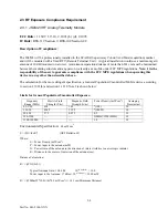
GENERAL SPECIFICATIONS

These specifications are subject to change without notice.

GENERAL JSLM2 INFORMATION


Frequency Range

137-162 MHz, 150-174 MHz, 450-470 MHz, 406-430 MHz

Frequency Control

Synthesized

Operating Voltage 

6 -15 VDC                                                                                                                                                                                                                                                                                                                                                                                     

Channel Spacing

12.5 kHz

Mode of Operation

Simplex or Half Duplex

RF Input/Output

BNC Jack

Power and Data Interface

DA-15 (15 pin D)

Receive Current Drain

<100 mA (w/o Field Programming Software Cable)

Transmit Current Drain

1200 mA max @ 7.2 VDC, <2000 mA max @ 12.5 VDC

Operating Temperature

-30

°

 to +60

°

 C (-22

°

 to +140

°

 F)

Maximum Dimensions

1.0" (H) x2.5”(W) x 3.7”(L)[2.54cm (H) x 6.35 cm (W) x 9.40 cm (L)]

Weight

8 oz.

Regulatory

FCC, Industry Canada

RoHS

The JSLM2 is not a RoHS compliant product 

JSLM2 RECEIVER

Bandwidth

UHF: 16 MHz (-210) 20 MHz (-510) VHF: 24 MHz (610), 25 MHz (710)

Frequency Stability

±

1.0 PPM

Sensitivity -12 dB SINAD

<-116 dBm

RF Input Impedance

50 ohms

Selectivity

60 dB (12.5 kHz)

Spurious and Image Rejection

70 dB 

Intermodulation

70 dB

FM Hum and Noise

40 dB (12.5 kHz)             

Conducted Spurious

<-57 dBm                                                                                                                                                          

Receive Carrier Detect

<3ms to 50% rated audio out with a -80 dBm RF input from audio squelch

Cold Start

<40 ms from power on cold start to carrier detect with a -80 dBm RF input

RECEIVE AUDIO RESPONSE referenced to 1 kHz tone 
Auxiliary Out w/o de-emphasis

+1/−3

 dB from 300 Hz to 2.5 kHz

Auxiliary Out with de-em1.5/-3 dB with 6 dB de-emphasis
Audio Out

+1/-3 dB with 6 dB de-emphasis

RECEIVE  AUDIO  OUTPUT  LEVEL  @  1  kHz  tone  60%  rated  deviation  (factory  set  levels)                                                                                                                                                                                       
Auxiliary Out w/o de-emphasis    212 mVrms +18 mV, 0.60 Vp-p 

±


0.05 Vp-p, into 600 ohm, AC Coupled                                                                                                                                     

Auxiliary Out with de-emphasis 160 mVrms +18 mV, 0.45 Vp-p 

±


0.05 Vp-p, into 600 ohm, AC Coupled                                                                                                                                               

Audio Out 

212 mVrms +18 mV, 0.60 Vp-p 

±


0.05 Vp-p, into 2k ohm, AC Coupled  

RECEIVE AUDIO OUTPUT MIN./MAX. ADJUSTMENT RANGE 1 kHz tone 60% rated deviation
Auxiliary Out w/o de-emphasis

50-400 mVrms into 600 ohm load

Auxiliary Out with de-emphasis 50-300 mVrms into 600 ohm load
Audio Out

50-212 mVrms into 2k ohm load

RECEIVE AUDIO DISTORTION


Auxiliary Out

<3%(Psophometrically weighted)  

Audio Out

<3%(Psophometrically weighted)

JSLM2 TRANSMITTER

Bandwidth

UHF: 16 MHz (-210) 20 MHz (-510) VHF: 24 MHz (610), 25 MHz (710) 

Frequency Stability

±

1.0 PPM

TCXO Coupling                           DC
RF Power Output

Programmable 0.10 to 2.00 @ 7.2 Vdc


Programmable 0.50 to 5.00 Watts @ 12.5 Vdc

Summary of Contents for JSLM2

Page 1: ...Part Number 001 2140 101 Revision 000 September 2005 Copyright 2005 Dataradio COR Ltd Synthesized UHF Telemetry Transceiver Synthesized Analog Radio...

Page 2: ...Part Number 001 2100 XXX Revision 000 May 2006 Copyright 2006 Dataradio COR Ltd...

Page 3: ...t and most trusted in the industry Product Warranty The manufacturer s warranty statement for this product is available in our manuals or by contacting Dataradio COR Ltd 299 Johnson Avenue Suite 110 W...

Page 4: ...AND VSWR 2 1 CONNECTOR J204 USER INTERFACE 2 1 GENERAL PINOUT DESCRIPTION 2 2 2 3 RF EXPOSURE COMPLIANCE REQUIREMENT 2 4 JSLM 2 VHF ANALOG TELEMETRY MODULE 2 4 JSLM 2 UHF ANALOG TELEMETRY MODULE 2 4 3...

Page 5: ...OFTWARE START UP SCREEN 3 2 3 3 SETUP JSLM2 PARAMETERS SETTINGS TAB 3 3 3 4 SETUP RADIO PARAMETERS SCREEN 3 5 3 5 SETUP FREQUENCIES SCREEN 3 6 3 6 JSLM2 VERSION REQUEST 3 7 3 7 SERIAL PC PORT SETTINGS...

Page 6: ...3 Part No 001 2100 XXX Revision History MAY 2006 Revision 000 Manual release...

Page 7: ...he 8 channel Loader Board which performs synthesizer loading The Loader Board has circuitry which provides transmit receive audio conditioning and gating carrier detect and RSSI buffering The gating c...

Page 8: ...e to interface the JSLM2 with the external 1200 Baud Modem Figure 1 1 JSLM2 Telemetry Module Table 1 1 ACCESSORIES Accessory Part No JSLM2 Programming Kit 250 2100 001 External 1200 Baud Modem 250 328...

Page 9: ...turning a product mark the RMA clearly on the outside of the package Include a complete description of the problem and the name and telephone number of a contact person RETURN REQUESTS WILL NOT BE PRO...

Page 10: ...t 3ms to 50 rated audio out with a 80 dBm RF input from audio squelch Cold Start 40 ms from power on cold start to carrier detect with a 80 dBm RF input RECEIVE AUDIO RESPONSE referenced to 1 kHz tone...

Page 11: ...y weighted TRANSMIT ATTACK TIME 15 ms from PTT to 100 rated power out MODULATION CAPABILITY MIN MAX ADJUSTMENT Auxiliary In w o pre emphasis 10 80 mVrms electronically programmable Auxiliary In with p...

Page 12: ...put Power vs Supply Voltage VHF Power W vs Supply Vdc 0 1 2 3 4 5 6 0 2 4 6 8 10 12 14 16 Supply Vdc Power W Power W vs Supply Vdc VHF Tx Current A vs Supply Vdc 0 0 0 5 1 0 1 5 2 0 5 7 9 11 13 15 17...

Page 13: ...vs Supply Voltage UHF Power W vs Supply Voltage V 0 1 2 3 4 5 6 5 7 9 11 13 15 17 Supply Vdc Power W Power W vs Supply Voltage V UHF Tx Current A vs Supply Voltage V 0 0 0 5 1 0 1 5 2 0 5 7 9 11 13 15...

Page 14: ...hnical Support Application note to interface the JSLM2 with the external 1200 Baud Modem 2 2 2 ANTENNA AND VSWR A VSWR measurement of the antenna system should be made before the module is put into se...

Page 15: ...ation PIN 8 RX Auxiliary Output AUX_OUT Audio from the receiver Without pre emphasis 212 Vrms 18 mV With pre emphasis 160 mVrms 18 mV Into a 600 ohm load PIN 9 Program I O From Computer PGM_IN_OUT TTL...

Page 16: ...re PIN 14 Push To Talk PTT_RTS TTL Keys the transmitter Can be active high or low set with software Internal 10k ohm pullup Pin 15 Ground Figure 2 2 JSLM2 Accessory Interconnect Power Cable 5 BLU BLK...

Page 17: ...way other than described above The calculation for the more stringent specification a General Population Uncontrolled Mobile device according to section 2 1091 b and section 1 1310 Note 2 is shown be...

Page 18: ...for the more stringent specification a General Population Uncontrolled Mobile device according to section 2 1091 b and section 1 1310 Note 2 is shown below Limits for General Population Uncontrolled...

Page 19: ...FIELD PROGRAMMING SOFTWARE 3 2 1 INTRODUCTION The JSLM2 Programmer is the Field Programming Software for tuning and programming the Dataradio JSLM2 series data transceiver see Figure 3 2 The Field Pr...

Page 20: ...e extension by selecting Save Data File from the file menu These programmable parameters are used by the Read Write Parameters screen for programming into nonvolatile memory of the JSLM2 3 2 2 1 SETTI...

Page 21: ...ield Mic Mute Mic Mute allows the user to enable or disable the microphone audio input The default for MIC input is enabled box checked to prevent stray noise pickup MIC Input J204 Pin 4 is passed thr...

Page 22: ...able from J204 Pin 11 When the RSSI Analog Out is enabled checked J204 Pin 11 is switched from Squelch Disable to a Receive Signal Strength Indicator RSSI DC voltage LED Enable The default value for L...

Page 23: ...shows the frequency range of the JSLM2 The frequency range is uploaded from the JSLM2 or from an opened file No entry is allowed in this field Synthesizer Type Shows the synthesizer type for the JSLM2...

Page 24: ...ates the RSSI level for a lost carrier The Carrier Detect Off Threshold value should be less than a larger negative number the Carrier Detect On Threshold value 3 2 2 3 FREQUENCIES TAB The Frequencies...

Page 25: ...D WRITE PROGRAMMABLE SETTINGS Read Programmable Settings Read Programmable Settings reads and displays the programmable settings currently programmed in the EEPROM of the JSLM2 Write Programmable Sett...

Page 26: ...number of Data Bits 4 8 to transmit or receive over the Primary and Secondary COM ports Parity The Parity field permits the user to select Parity Bits None Odd Even to transmit or receive for the Pri...

Page 27: ...the carryout of the high order bits When using a Sync Esc Framing Mode the Field Programming Software will stuff this character automatically Swap COM Ports Swap COM Ports allows the user to swap the...

Page 28: ...om the PC DTR The DTR field shows the current state of the DTR data terminal ready line DTR is an output from the PC CTS The CTS field shows the current state of the CTS clear to send line CTS is an i...

Page 29: ...re in Celsius RSSI Level Received Signal Strength indicator in volts RSSI Level Received Signal Strength indicator in dBm Power Set Transmitter power digipot setting Tx Dev Level Set Transmitter modul...

Page 30: ...les the default setting Tx Deviation Level The Tx Deviation Level slider bar allows the user to change the Tx Deviation Level Rx Auxiliary Level The Rx Auxiliary Level slider bar allows the user to ch...

Page 31: ...send and receive ASCII data on the Primary COM port setup the Port Settings Secondary selects an ASCII Terminal screen to send and receive ASCII data on the Secondary COM port setup in Port settings...

Page 32: ...or normal Bell 202 or Bell 103 format All data parameters are set using an eight position DIP switch located inside the modem Programming RNet JSLM Transceiver The RNet JSLM transceiver is computer pr...

Page 33: ...er Manual 001 2100 XXX Failure to observe the maxi mum duty cycle could result in premature transmitter failure Dataradio recommends storing the programming software on the hard drive of the computer...

Page 34: ...ommended JSLM2 Programming Settings for interfacing with DL 3282 Modem CD Carrier Detect Active high Settings tab RS Ready to Send Active high Settings tab PTT Push to Talk Active low Settings tab Mic...

Page 35: ...Products if i the Product has been used in other than its normal and customary manner ii the Product has been subject to misuse accident neglect or damage or has been used other than with DRL approve...

Reviews: