


2-2
Part No. 001-2100-XXX
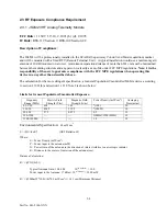
2.2.4 GENERAL PINOUT DESCRIPTION
Table 2-1 Channel Select Table
CSO_N.... CS2_N
internally pulled up to 5 VDC, ground pin for logic low
.
PIN 1: Channel Select 0 (CSO_N)
Switch 0
PIN 2: Channel Select 1 (CS1_N)
Switch 1
PIN 3: Channel Select 2 (CS2_N)
Switch 2
PIN 4: TX Microphone Input (MIC_IN)
30 mVrms nominal for 60% rated deviation.
PIN 5:
Connected internally to Pin 1
PIN 6: Raw Battery Supply (7.2 or 12.5 VDC nominal)
Power supply 6-15 VDC, 3 Amps maximum.
PIN 7: TX Auxiliary Input (AUX_IN)
Audio input for the transmitter.
Without pre-emphasis: 40 mVrms nominal for 60% rated deviation.
With pre-emphasis: 200 mVrms nominal for 60% rated deviation.
PIN 8: RX Auxiliary Output (AUX_OUT)
:
Audio from the receiver.
Without pre-emphasis: 212 Vrms
±
18 mV
With pre-emphasis: 160 mVrms
±
18 mV
Into a 600 ohm load
PIN 9: Program I/O From Computer
(PGM_IN_OUT)
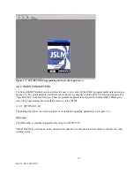
(TTL) The Interface cable (see Table 1-1) converts RS-232 to TTL logic for JSLM2
programming information.
PIN 10: Ready to Send (RS)
(TTL) Radio is locked on frequency and transmitter is ready to accept audio input,
set with software active high or low.
PIN 11: _Squelch_Disable/RSSI Out
User programmable to:
Squelch Disable
- When the Squelch Disable box is unchecked, the receive audio is squelched. Grounding
Pin 11 will un-squelch the receive audio
RSSI Analog Out
- RSSI DC output voltage level
PIN 12: RX Audio Out (AUDIO_OUT)
Audio Output 212 mVrms +18 mV into a 2000 ohm load.
CH
CSO_N
CS1_N
CS2_N
1
0
0
0
2
1
0
0
3
0
1
0
4
1
1
0
5
0
0
1
6
1
0
1
7
0
1
1
8
1
1
1