background image

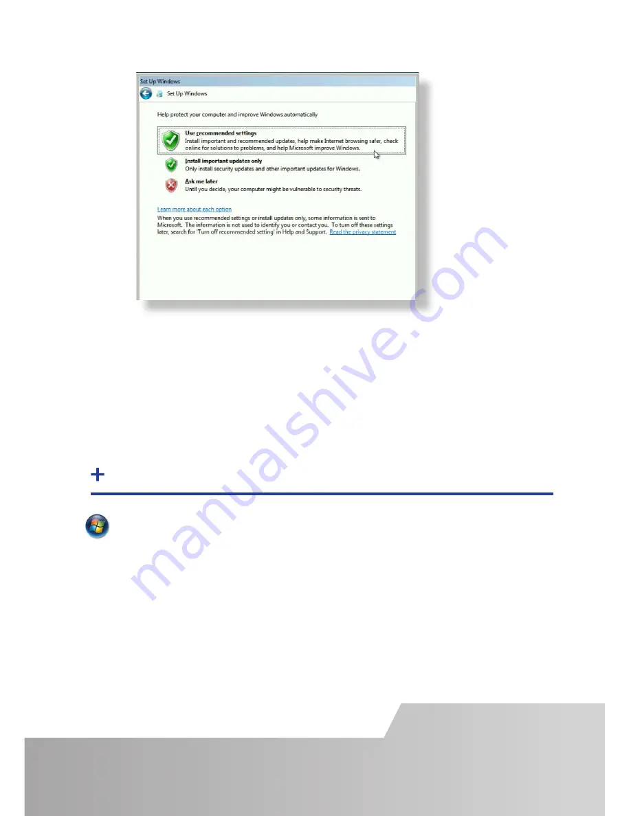
Start | Computer | System Properties | Activate Windows now.

Select the appropriate method available.  

To view the product key, gently pull away the front panel of the VSNMicro 600.  The 
front panel is held in place using a series of magnetic points. 


STEP 8 ACTIVATE WINDOWS 7

Page 9

Computer Name:  

I

t is recommended that only Internet-standard characters are used in the computer 

name.  The standard characters are the numbers 0 through to 9, upper and  
lower-case letters from A through to Z and the hyphen character.  Computer names 
can’t consist entirely of numbers nor can they contain spaces.  The name also can’t 
contain special characters such as:   < > ; : “ ?* + = \ | ? ,.

Summary of Contents for VSNMicro N600

Page 1: ...er The aim of this document is to quickly guide you through the process of initial setup For detailed instructions consult the system User Guide which can be found on the Recovery Media Quick Start Guide www datapath co uk sales datapath co uk 44 0 1332 294441 600 ...

Page 2: ...ack PCIe card product leaflets Build Log MAC Address labels Each DatapathVSNMicro 600 is custom built and therefore the number and type of input and output cards will differ from system to system Contained with this Quick Start Guide are PCIe card product leaflets which give details on how the cards are installed and any accessories which may accompany them Page 2 ...

Page 3: ...Connect Keyboard and Mouse to USB Ports STEP 2 KEYBOARD AND MOUSE STEP 3 CONNECT TO A NETWORK OPTIONAL Page 3 ...

Page 4: ... and type of inputs will differ from system to system Contained within the documentation pack is a Build Log detailing the PCIe cards installed and where they are located on the backplane The enclosed Product leaflets give details on how the cards are connected Input Connectors ...

Page 5: ...he motherboard as shown above If a control screen is not required the BIOS settings will require changing For instructions consult the system User Guide which can be found on the Recovery Media Page 5 1 4 Monitor 2 Monitor 3 Monitor 4 Monitor 5 Monitor 7 Monitor 6 Monitor 8 Monitor 1 Connect graphic outputs to monitors using DisplayPort cables Not supplied Control Screen Optional 4 x 2VideoWall 1 ...

Page 6: ...l the packaging and carefully slide them into the power supply unit on the rear of the system with the protective grill uppermost You will feel and hear a firm click when they are in place For detailed instructions on how to fit the Power Supply Modules see the PDF User Guide which can be found on the Recovery Media Never use force when inserting the Power Supply Modules as this can cause damage n...

Page 7: ...Connect power cables single cable for ATX then plug into and turn on the mains supply 2 Switch on the system 3 Page 7 ...

Page 8: ...Page 7 Page 8 The Product key is located behind the front panel Gently pull away the panel for access STEP 7 WINDOWS 7 SETUP ...

Page 9: ...es of magnetic points STEP 8 ACTIVATE WINDOWS 7 Page 9 Computer Name It is recommended that only Internet standard characters are used in the computer name The standard characters are the numbers 0 through to 9 upper and lower case letters from A through to Z and the hyphen character Computer names can t consist entirely of numbers nor can they contain spaces The name also can t contain special ch...

Page 10: ... configured settings for the wall layout and screen resolution You can change these settings if required using theTWIN tab Start Control Panel Appearance and Personalization Adjust screen resolution 1 2 3 STEP 9 DISPLAY SETUP Page 7 Page 10 ...

Page 11: ...haracters are the numbers 0 through to 9 upper and lower case letters from A through to Z and the hyphen character Computer names cannot consist entirely of numbers contain spaces or use special characters such as There is no requirement for users to activateWindows 10 activation is completed automatically Enter localisation details Page 11 ...

Page 12: ...Start Control Panel Display Change Display Settings 1 STEP 11 DISPLAY SETTINGS WINDOWS 10 2 3 4 Page 12 ...

Page 13: ...ed to 2 A representation of the display wall associated with the server 3 SourcesTab Displaying all the sources connected to the server for use on your display wall 4 LayoutsTab Use to save recall and share display wall layout configurations 5 TemplatesTab Use templates to assist in the design of specific display wall layouts Start All Programs WallControl 10 Server Before opening the Client inter...

Page 14: ...ck on the required source in the SourcesTab and drag it onto the display wall representation The application help file contains information explaining how multiple sources can be selected how to use and create templates and how to save recall and share layout files Note If you haveWall Control red installed please refer to theVSNMicro 600 User Guide which can be found on the Recovery Media Sources...

Page 15: ... or omis sions Datapath reserves the right to change specification without prior notice and cannot assume responsibility for the use made of the information supplied All registered trademarks used within this documentation are acknowledged by Datapath Limited EU Class A Declaration of Conformity Datapath Ltd declares that this product complies with the essential requirements and other relevant pro...

Page 16: ...and 44 0 1332 294441 sales datapath co uk Datapath North America 2550 Blvd of the Generals Suite 320 Norristown PA 19403 USA 1 484 679 1553 sales datapath co uk Datapath France 33 1 3013 8934 sales fr datapath co uk Datapath Germany 49 1529 009 0026 sales de datapath co uk Datapath China 86 187 2111 9063 sales cn datapath co uk Datapath Japan 81 0 80 3475 7420 sales jp datapath co uk ...

Reviews: