background image

M-Series QuickStart Guide

Datalogic M5xx Camera

Page 21

Datalogic Automation, Inc.

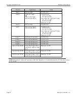
NOTE 1

: To help prevent ground loops and possible false triggering, we recommend connecting I/O Ground to Camera 

Power Ground.

Input 2 -

No Connection

DO NOT USE

Input 2 +

Single Line Trigger 

OR

Phase A Line Trigger 
(Quadrature Encoder)

As sinking input

   Off 0 to +0.8 VDC
   On: +2.0 to +5 VDC

As sourcing input (see Input 2 Pullup)

   Off: +2.0 to +5 VDC
   On 0 to +0.8 VDC
Maximum: +5 VDC

Input 3 -

No Connection

DO NOT USE

Input 3 +

Phase B Line Trigger 
(Quadrature Encoder) 

As sinking input

   Off 0 to +0.8 VDC
   On: +2.0 to +5 VDC

As sourcing input (see Input 3 Pullup)

   Off: +2.0 to +5 VDC
   On 0 to +0.8 VDC
Maximum: +5 VDC

Output 1 -

Not Currently Supported

DO NOT USE

Output 1 +

Not Currently Supported

DO NOT USE

Output 2 -

Not Currently Supported

DO NOT USE

Output 2 +

Not Currently Supported

DO NOT USE

Input 1 5VDC

Frame Start Trigger Pullup - 
use if Input 1 needs sourcing 
input

Maximum: +5 VDC

Input 2 5VDC

Line Trigger Pullup - use if 
Input 2 needs sourcing input

Maximum: +5 VDC

Input 3 5VDC

Line Trigger Pullup - use if 
Input 3 needs sourcing input

Maximum: +5 VDC

Terminal

Signal Name

Notes

Summary of Contents for M-Series

Page 1: ...M Series QuickStart Guide Publication Number 843 0151 Rev J...

Page 2: ...trol Panel Manager CPM Digital Serial Link Pinpoint Pattern Find and DSL are trademarks of Datalogic Automation Inc Microsoft Windows is a trademark of Microsoft Corporation Java is a trademark of Sun...

Page 3: ...for later use Follow all warnings and instructions in this manual and in other user guides shipped with your hardware compo nents To avoid damage to the vision system and its components never plug in...

Page 4: ...vice Software is intended for installation only on a Datalogic M Series processor You must install it directly on the processor you intend to use You cannot install it remotely When a new processor is...

Page 5: ...Area Connection LAN1 or LAN2 and select Properties 3 On the General tab select Internet Protocol TCP IP and click Proper ties 4 On the General tab select Use the fol lowing IP address 5 Enter the des...

Page 6: ...ries QuickStart Guide Datalogic Automation Inc Page 4 5 In the list of items select Internet Protocol Version 4 TCP IPv4 then click Properties 6 Select Use the following IP address 7 Enter the desired...

Page 7: ...nt facing upward so the CF card does not fall out due to vibration To mount the Processor using the mounting brackets 1 Fasten the two mounting brackets to the bottom of the Processor using the bracke...

Page 8: ...he desired bracket orientation horizontal or vertical The part of the bracket that contains the butterfly clip should be on the bottom 2 Fasten the bracket holding plate onto the bottom of the process...

Page 9: ...is enclosure This connection is needed to insure electromagnetic compliance and proper operation The MX20 and MX40 processors require approxi mately 10A 10VDC 3 5A 24VDC and 3A 30VDC Datalogic recomme...

Page 10: ...0 and MX40 Front Panel Connections This is the MX20 and MX40 Processor s front panel Note If a Compact Flash card is present in the socket it can be used for extended storage by the MX20 and MX40 pro...

Page 11: ...card while the unit is powered on Symbol Function A USB Port B Serial Port 2 C Speaker and Microphone D Power Switch Symbol Function A Status Lights see Page 11 B Power Button C Reset Button Resets th...

Page 12: ...aker and Microphone Symbol Name When lit indicates A PoE MX40 4 MX20 2 Power over Ethernet PoE is active M1xx camera only B Power Power is On C HDD Blinking Solid state hard drive is active D PoE Acti...

Page 13: ...ve is active C Power Power is On D PoE 4 Power over Ethernet PoE is active M1xx camera only E PoE Activity Link 4 On Link is established Blinking Data is being transferred F PoE Speed 4 Off 10 Mbps Gr...

Page 14: ...Processor power and input output signals use cable 606 0675 xx 37 pin D sub Male to Male with terminal block 661 0403 Input Characteristics The diagrams and table below describe the input characteris...

Page 15: ...ors contain sixteen general purpose output connections NOTES An external power source is required to power an output load The outputs are merely switches that are open or closed All output connections...

Page 16: ...mally high and goes low when On The Discrete Output tool in the vision pro gram must be programmed to provide the desired output level Refer to Discrete Output tool in the Impact Reference Guide 843 0...

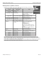
Page 17: ...Notes Optional Camera Power 12VDC Camera Power Required when NOT using Power Over Ethernet PoE 12 VDC 10 250 mA Max Maximum 13 2 VDC Minimum 11 3 VDC Optional Camera Power Ground Camera Power Ground...

Page 18: ...e cameras Trigger In Camera Trigger In 0 to 24 VDC recommended Maximum 30 VDC As sinking input Off 0 to 1 4 VDC On 2 2 to 24 VDC 5 to 15 ma As sourcing input see Trigger Pullup VCC Off 2 2 to 24 VDC 5...

Page 19: ...M Series QuickStart Guide Datalogic M1xx Camera Page 17 Datalogic Automation Inc M1xx Strobe Trigger Output Circuit M1xx Terminal Connections...

Page 20: ...Ground Camera Ground I O Ground I O Ground Camera Power VDC Camera Power 12 to 24 VDC recommended 500 mA Max Maximum 30 VDC Output VCC Power for Strobe Trigger Out 3 3 to 24 VDC 50 mA Max Maximum 30 V...

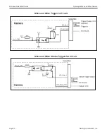
Page 21: ...M Series QuickStart Guide Datalogic M2xx and M3xx Camera Page 19 Datalogic Automation Inc M2xx and M3xx Trigger In Circuit M2xx and M3xx Strobe Trigger Out Circuit...

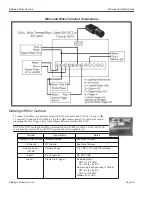
Page 22: ...Impact Reference Guide 843 0093 NOTE Do NOT use the M2xx M3xx terminal block 661 0400 or M1xx block 661 0399 to connect this camera They will NOT provide the correct signal levels Terminal Signal Name...

Page 23: ...OT USE Input 3 Phase B Line Trigger Quadrature Encoder As sinking input Off 0 to 0 8 VDC On 2 0 to 5 VDC As sourcing input see Input 3 Pullup Off 2 0 to 5 VDC On 0 to 0 8 VDC Maximum 5 VDC Output 1 No...

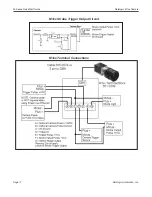
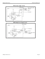
Page 24: ...Datalogic M5xx Camera M Series QuickStart Guide Datalogic Automation Inc Page 22 M5xx Frame Trigger Circuit M5XX Single Line Trigger Circuit...

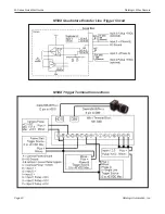
Page 25: ...M Series QuickStart Guide Datalogic M5xx Camera Page 23 Datalogic Automation Inc M5XX Quadrature Encoder Line Trigger Circuit M5XX Trigger Terminal Connections...

Page 26: ...Datalogic M5xx Camera M Series QuickStart Guide Datalogic Automation Inc Page 24...

Reviews: