


Datalogic M5xx Camera
M-Series QuickStart Guide
Datalogic Automation, Inc.
Page 20
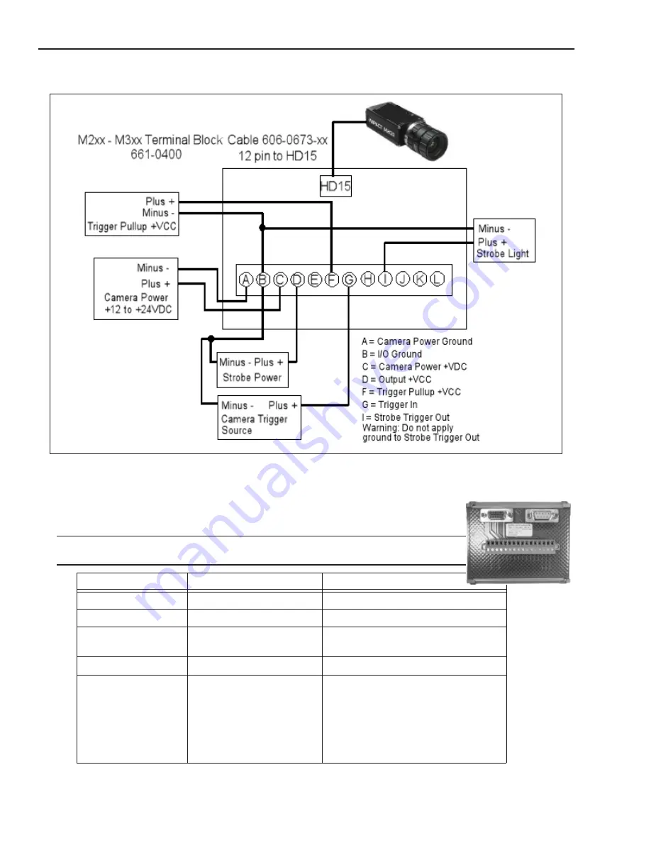
M2xx and M3xx Terminal Connections
Datalogic M5xx Camera
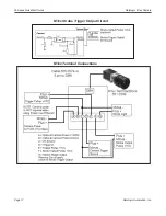
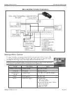
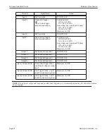
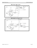
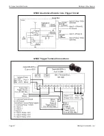
To connect the M5xx, use terminal block 661-0401 with cable 606-0673-xx (12-pin to HD-
15 camera I/O) and cable 606-0674-xx (6 pin to DB9 camera power). For details about pro-
gramming the Line Trigger, refer to the Impact Reference Guide (843-0093).
NOTE: Do NOT use the M2xx/M3xx terminal block (661-0400) or M1xx block (661-0399)
to connect this camera. They will NOT provide the correct signal levels.
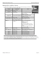
Terminal
Signal Name
Notes
Camera Power Ground
Camera Ground
See Note 1 Below
I/O Ground
I/O Ground
See Note 1 Below
Camera Power
+12VDC
Camera Power
+12 VDC (+-10%) @ 700 mA Max
Input 1 -
No Connection
DO NOT USE
Input 1 +
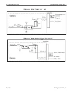
Frame Start Trigger
As sinking input
Off 0 to +0.8 VDC
On: +2.0 to +5 VDC
As sourcing input (see Input 1 Pullup)
Off: +2.0 to +5 VDC
On 0 to +0.8 VDC
Maximum: +5 VDC


