DS6400 QUICK GUIDE
27
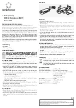
READING DIAGRAMS
DS6400-105-0XX (Oscillating Mirror) – Resolution: 0.50 mm/20 mils
CONDITIONS
Code = Interleaved 2/5 or
Code 39
PCS = 0.90
Pitch angle = 0°
Skew angle = 10° - 20°
Tilt angle = 0°
8
4
12
(in)
0 16
28
(in)
20
24
32 36
0 40 50
60
70 80 90 100 110
(cm)
50
40
30
20
0
(cm)
10
-10
0
-20
-30
-40
16
20
-16
-20
-12
-8
-4
120 130
44
40
48
52
-50
-24
60
24
140 150
60
56
Global Reading
Area
-60
Focus
Pos ition = 115 c m
160
64
170 180
68 72
70
28
-70
-28
190
76
200
80
60
56
130
64
(in)
160
150
52
(cm)
140
120
110
100
90
80
36
32
40
44
48
70
28
0
50
60
70
80
90 100 110 120
(cm)
130 140 150 160 170
20
32
(in)
24
28
36
40
48
44
52 56
64
60 68
60
50
40
24
20
16
Max. Reading
Distance
Reading distance
Focus Distance
180
68 170
72 180
72
40
16
76 190
Min. Reading
Distance