


RAPID CONFIGURATION
1
STEP 3 – X-PRESS™ CONFIGURATION
X-PRESS™ is the intuitive Human Machine Interface designed to improve ease of
installation and maintenance.
Status and diagnostic information are clearly presented by means of the five colored
LEDs, whereas the single push button gives immediate access to the following
relevant functions:
•
Test Mode (F1)
with bar graph visualization to
check static reading performance
•
AutoLearn
(F2)
to self-detect and auto-configure
for reading unknown barcodes (by type and
length)
•
AutoSetup
(F3)
to self-optimize and auto-
configure reading performance in demanding
applications
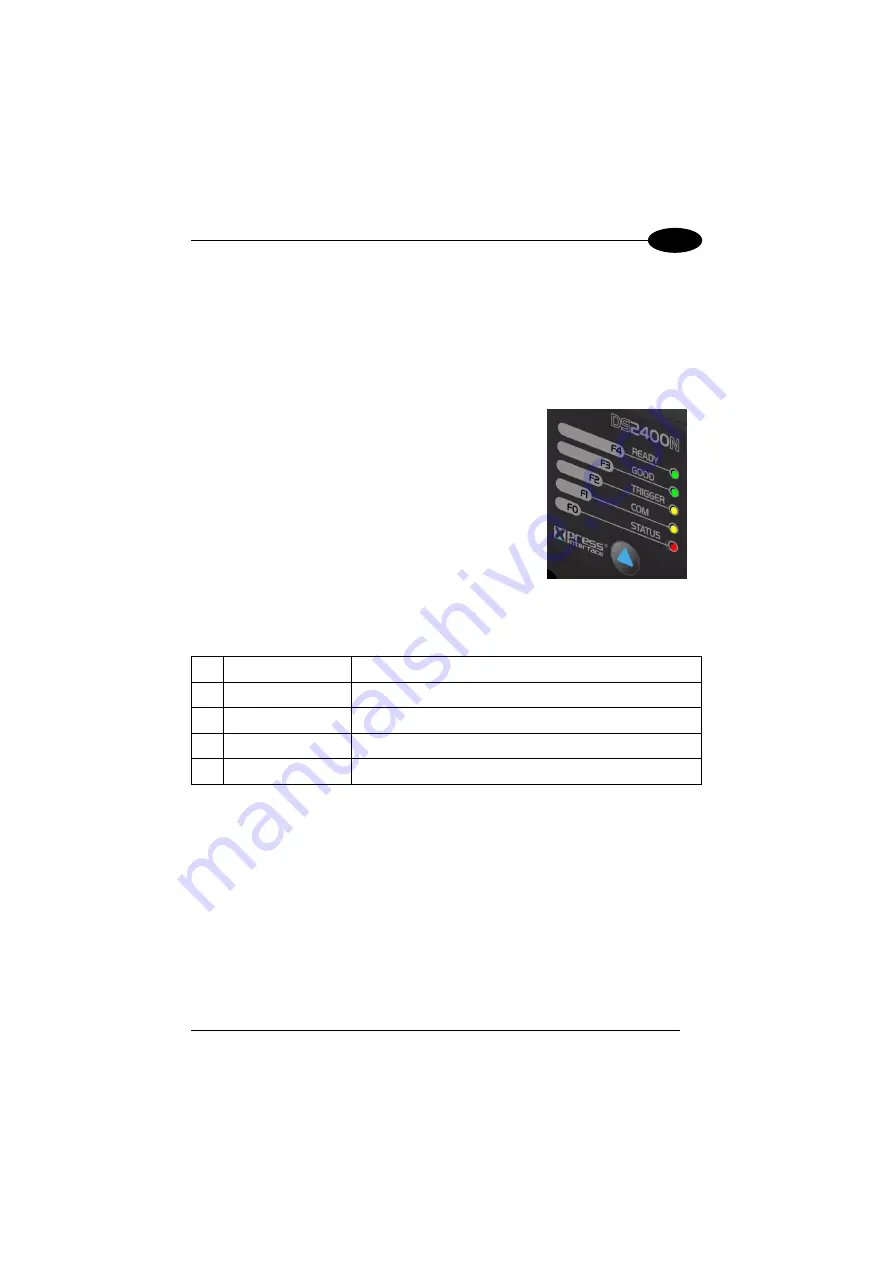
The colors and meaning of the five LEDs are illustrated in the following table:
F4
READY (green)
This LED indicates the device is ready to operate.
F3
GOOD (green)
This LED confirms successful reading.
F2
TRIGGER (yellow)
This LED indicates the status of the reading phase.
F1
COM (yellow)
This LED indicates active communication on main serial port.
F0
STATUS (red)
This LED indicates a NO READ result.
During the reader startup (reset or restart phase), all the LEDs blink for one second.
On the back of the reader near the cable, the “POWER ON” LED indicates the laser
scanner is correctly powered.
5
Summary of Contents for DS2400N
Page 1: ...DS2400N REFERENCE MANUAL ...
Page 5: ...GLOSSARY 70 INDEX 74 v ...
Page 10: ...x ...
Page 20: ...DS2400N 1 b Operating mode selection and definition c Digital Outputs configuration 10 ...
Page 49: ...INSTALLATION 3 Figure 23 ID NET Network Connections with isolated power blocks 39 ...
Page 50: ...DS2400N 3 Figure 24 ID NET Network Connections with Common Power Branch Network 40 ...
Page 51: ...INSTALLATION 3 Figure 25 ID NET Network Connections with Common Power Star Network 41 ...


