


INSTALLATION
11
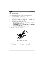
2
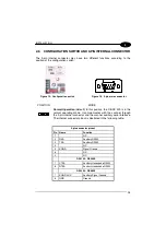
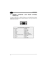
The C-BOX 3X0 spring clamp connector pinouts are indicated in the following table.
Refer to the scanner Installation Manual for details.
Pin
Name
1, 3, 5
VS
2, 4, 6
GND
7, 8
EARTH GROUND
9…12, 20, 33, 34, 40
Reserved
21
OUT1+
23
OUT2+
27
EXT TRIG+
28
EXT TRIG-
35
TXA
37
RXA
39
SGND
DS2100
DS2400
DS4300
DS4600
22
OUT REF
OUT1-
24
OUT REF
OUT2-
25, 26
NC
Reserved
29
NC
IN1+
30
NC
IN1-
31
NC
IN2+
32
NC
IN2-
36
RTSA
GND
38
CTSA
SGND AUX
NOTE
Pin 7 or 8 should be connected to the earth ground.
Pins 13… 19 are not present in the C-BOX 3X0 models.


