


INSTALLATION
7
2
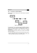
2.5 ELECTRICAL CONNECTIONS AND SETUP
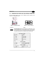
The following figure shows the typical layout.
PROFIBUS
MASTER
C-BOX 3X0
SCANNER
System
Cables
Figure 7 – System layout
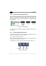
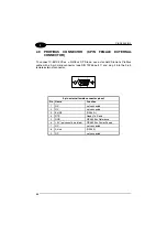
A PC can be connected to the C-BOX 3X0 (and consequently to the scanner
auxiliary interface) through the internal 9-pin connector. This allows monitoring of the
data transmitted by the scanner or configuration through the WinHost utility (see the
scanner Installation Manual for more details). The scanner auxiliary interface signals
are also available on the internal spring clamp connectors.
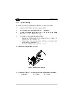
After making system cabling and switch settings (see sub-paragraphs under 2.5),
connect the scanner to the 25-pin connector on the left side of the C-BOX 3X0
housing.
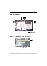
Switch ON the C-BOX 3X0 power switch (see Figure 8).
By default, after power on, an automatic connection procedure takes place between
the C-BOX 3X0 and the scanner. During this phase, requiring a few seconds, the
warning LED is turned ON. Once the procedure had been completed successfully,
the warning LED is turned OFF.
To disable this automatic connection procedure, refer to WinHost Help Online.
After system functioning has been verified, close the C-BOX 3X0 using the 4 cover
screws making sure the rubber seal is fitted correctly between the parts of the
housing.