


C-BOX 300/310
10
2
2.5.2 System
Wiring
The connection and wiring procedure for C-BOX 3X0 is described as follows:
1)
Open the C-BOX 3X0 as described in paragraph 2.2.
2)
Verify that the C-BOX 3X0 power switch is off (see Figure 8).
3)
Unscrew the compression connectors and pass all the system cables
through them into the C-BOX 3X0 housing.
4)
To connect the power and input/output signals:
•
Prepare the individual wires of the system cables by stripping the
insulation back approximately 1 cm.
•
Using a device such as a screwdriver, push down on the lever directly
next to the clamp (see Figure 10).
•
Insert the wire into the clamp and release the lever.
The wire will now be held in the spring clamp.
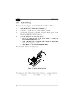
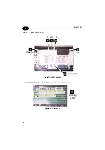
Figure 10 - System cable connections
The wiring used can be solid or stranded but must meet the following specifications.
All positions:
24 - 16 AWG
0.2 - 1.5 mm²


