background image

DKG-119J User Manual                                                                        V-32 

(09.07.2012)


- 9 -


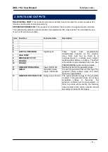
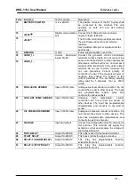
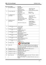
Screen  Description 

Contents 

Genset parameters 

Genset status 
Engine rpm,                                 Genset Frequency 
Genset Current L1,                      Genset Volts L1 
Genset power factor,                   Genset Active Power (KW) 

Engine parameters 
 

Genset status 
Oil Pressure,                               Engine rpm 
Coolant Temperature,                 Battery Voltage 
Fuel Level, 

Complete Genset 
parameters 
 

Genset status 
Engine rpm,                                 Genset Frequency,                     
Genset Volts L1,                          Oil Pressure 
Genset Current L1,                      Coolant Temperature 
Genset Active Power (KW),        Fuel Level 
Genset power factor,                   Battery Voltage 

Graphical Genset 
parameters 
 

Genset status 
                                                     Genset Volts L1 
                                                     Genset Current L1 
Genset Active Power (%),            Genset Frequency 
                                                     Oil Pressure  
                                                     Coolant Temperature 
                                                     Fuel Level 

CANBUS Measurements 
             1 / 6 

Percent Torque 
Percent Load 
Fuel Pressure 

CANBUS Measurements 
             2 / 6 

Fuel Rate 
Average Fuel Economy 
Total Engine Hours 

CANBUS Measurements 
             3 / 6 

Air Pressure 
Ambient Air Temperature 
Oil Temperature 

CANBUS Measurements 
             4 / 6 

Intake Manifold 1 Temperature 
Exhaust Gas Temperature 
Fuel Temperature 

CANBUS Measurements 
             5 / 6 

Boost Pressure 
Air Filter Differential Pressure 
Crank Case Pressure 

10 

CANBUS Measurements 
             6 / 6 

Coolant  Level 
Oil Level 
Coolant Pressure 

11 

Company Logo 


12 

Alarm List 
 

If no alarm exists, „END OF ALARM LIST‟ will be displayed. 
Existing alarms, load_dumps, warnings will be displayed as 
one screen for each entry. Switching to the next entry will be 
made with the 

▼ button. 

13 

Software Version 

Operating software and J1939 software version. 

14 

Statistical Counters 1 / 3 
 

Engine Hours Run  
Total Genset Active Power (KW-h) 

15 

Statistical Counters 2/ 3 
 

Engine Hours to Service 
Time to Service 

16 

Statistical Counters 3 / 3 
 

Total Engine Cranks 
Total Engine Runs 

17 

Event Records 
 

The unit provides information about last  200 events, starting 
from the most recent one. 
Please review chapter 10 for detailed information about event 
logging. 

Summary of Contents for DKG-119J

Page 1: ...lable Mains simulation input Engine Idle speed control Periodic maintenance request Engine hours counter Event logging with complete measurement values Stores last 200 events Statistical counters 3 le...

Page 2: ...y Operation 6 10 Periodic Service Request Monitoring 6 11 Engine Hours Meter 6 12 Display of Software Version 6 13 SMS message sending 6 14 Remote Monitoring and Programming 6 15 External Control of t...

Page 3: ...ting set Programmed parameters are stored in a Non Volatile Memory and thus all information is retained even in the event of complete loss of power The measured parameters are Mains voltage phase L1 t...

Page 4: ...el do not connect the senders to the unit The unit is factory programmed for VDO type senders However different types of senders are selectable via programming menu Please check the programming sectio...

Page 5: ...closed or normally open contact switching either battery or battery The effect of the switch is also selectable from a list See PROGRAMMING section for more details 7 HIGH TEMP 8 EMERGENCY STOP 9 SPA...

Page 6: ...er The secondary winding rating shall be 5 Amperes For ex 200 5 Amps 19 CURR_1 20 FUEL LEVEL SENDER Input 0 5000 ohms Analogue fuel level sender connection Do not connect the sender to other devices T...

Page 7: ...flash Alarms work on a first occurring basis The occurrence of a fault will disable other faults of lower or equal priority SERVICE REQUEST Red Engine periodic maintenance request indicator It turns o...

Page 8: ...it will switch automatically between different screens displaying always the most important parameters for the current operating status If an alarm loaddump or warning occurs during operation in other...

Page 9: ...ours 7 CANBUS Measurements 3 6 Air Pressure Ambient Air Temperature Oil Temperature 8 CANBUS Measurements 4 6 Intake Manifold 1 Temperature Exhaust Gas Temperature Fuel Temperature 9 CANBUS Measuremen...

Page 10: ...ING led to be on steadily The Horn and Alarm Load_dump Warning digital outputs to operate if selected via programming menu If the ALARM MUTE button is long pressed the Horn output will be deactivated...

Page 11: ...delay after the engine is running Low and high limits for warning and alarm are separately programmable Another high frequency shutdown limit which is 12 above the high limit is always monitored and...

Page 12: ...period the generator contactor function is deactivated If a cooldown period is given the generator will continue to run during cooldown period At the end of the period the fuel solenoid will be de en...

Page 13: ...Ohms is also programmable Especially on engines without a body heater or with a failing one it may be desired that the genset should not take the load before reaching a suitable temperature The unit...

Page 14: ...it is adjusted using the parameter Engine Heating Temperature The same parameter is used for engine heating operation The relay will become active if the body temperature falls to 4 degrees below the...

Page 15: ...If the Simulate Mains input is defined and the input signal is active the mains phases are not monitored and supposed to be inside limits This will prevent the genset from starting even in case of a m...

Page 16: ...attery positive or battery negative These selections are made using the programming menu If the Delayed Simulate Mains program parameter is set to 1 and the input signal is active when the genset is n...

Page 17: ...ittent operation uses also the Mains Simulation feature Please review chapter 6 7 for a detailed explanation of this feature Priority In Dual Genset Mutual Standby Operation It may be required that th...

Page 18: ...ch to the ALARM LIST The service request relay function may be assigned to spare relays using Relay Definition program parameters Also relays on an extension module may be assigned to this function Th...

Page 19: ...sage is given below DKGxxx SITE ID STOP LOW OIL PRESSURE SW END OF ALARM LIST The first line of the message carries information about the unit type and the site identity string This line is intended f...

Page 20: ...ADAPTER PRODUCT CODE DA70146 REV 1 1 DIGITUS USB 1 1 TO RS 232 ADAPTER PRODUCT CODE DA70145 REV 1 1 FLEXY USB 1 1 TO SERIAL ADAPTER PRODUCT CODE BF 810 CASECOM USB TO SERIAL CONVERTER MODEL RS 01 The...

Page 21: ...ists on the disconnection of the least crucial loads when the genset power approaches to its limits These loads will be supplied again when the genset power falls below the programmed limit The intern...

Page 22: ...the sender input is increased more than this parameter in 1 hour period then a FUELLING sms message is sent to programmed telephone numbers The unit offers possibility of updating the firmware in the...

Page 23: ...e engine speed in the 8 range may be done using the program parameter J1939 Speed Adjust In engine control mode the unit is supposed to control an engine without alternator The engine control mode is...

Page 24: ...Voltage Limit Mains Low Frequency Limit Mains High Frequency Limit Genset Low Voltage Shutdown Limit Genset Low Voltage Warning Limit Genset High Voltage Warning Limit Genset High Voltage Shutdown Li...

Page 25: ...coolant temperature and the engine rpm information are picked up from the ECU unit Other available measurements are displayed for information but they have no effect on engine operation In total the...

Page 26: ...ensor fail 168 x Battery voltage failure 172 x High inlet air temperature High inlet manifold air temperature Inlet manifold air temperature sensor fail 174 x High fuel temperature Fuel temperature se...

Page 27: ...hanical fault Faulty response from mechanical system 8 Mechanical or electrical fault Abnormal frequency 9 Communication fault Abnormal updating rate or Open circuit in injector circuit 10 Mechanical...

Page 28: ...Reference Guide The web address is www modbus org docs PI_MBUS_300 pdf Below is a limited shortlist of readable registers For the detailed Modbus Application Manual and a complete list of registers p...

Page 29: ...tton switches the display to the previous page of the current event After the first page of the current event the last page of the next event is displayed Each event is displayed in 3 pages Event and...

Page 30: ...total genset KWh engine hours to service time to service total engine cranks total genset runs These counters are kept in a non volatile memory and are not affected from power failures Wipe the unit...

Page 31: ...n program groups and each group consists of various program parameters When program mode is entered a list of available groups will be displayed Navigation between different groups are made with and b...

Page 32: ...ine parameters large characters 2 screen 5 maximum information small characters 3 screen 6 analog power meter Details of each screen are explained in chapter 3 2 2 Engine Control Only 0 0 Genset contr...

Page 33: ...incremented by this value It is advised to set this value to 8 volts 2 RPM from genset frequency 1 This parameter is used in the conversion of the genset frequency to engine rpm 0 read rpm from the o...

Page 34: ...feeding the load this will generate a GENSET LOW VOLTAGE shutdown alarm and the engine will stop 2 Genset Low Voltage Warning Limit V 200 If one of the generator phase voltages goes under this limit...

Page 35: ...r this limit it means that the mains are off and it starts the transfer to the genset in AUTO mode 2 2 nd Mains Frequency Low Limit Hz 55 When secondary volt freq limits are active If the mains freque...

Page 36: ...tdown C 98 f the coolant temperature measured from the analog input goes over this limit this will generate a HIGH TEMPERATURE SENDER alarm and the engine will stop 2 Oil Pressure Sender type 1 This p...

Page 37: ...Timer 1 engine is heated until the coolant temperature reaches the Engine Heating Temperature and at least during the Engine Heating Timer 1 Service Engine Hours hour 50 The SERVICE REQUEST led indica...

Page 38: ...the coolant temp is below this limit then the fan relay function will become inactive 2 2 nd Low Frequency Shutdown Hz 40 When secondary volt freq limits are active If the genset frequency goes under...

Page 39: ...RKINS ADEM 1 3 96 VOLVO with CIU unit 97 VOLVO EMS2 98 VOLVO EDC4 112 CATERPILLAR ADEM II III 128 SCANIA S6 129 SCANIA Single Speed 130 SCANIA All Speed 144 IVECO 160 MTU MDEC 302 161 MTU MDEC 201 162...

Page 40: ...alue Oil Pressure Sender Ohms 6 ohm 184 Oil Pressure Sender point 6 ohm value Oil Pressure Value 6 bar 10 0 Oil Pressure Sender point 6 bar value Program Group Sender Characteristics password level 2...

Page 41: ...lly open 1 Normally closed Switching 0 0 Battery negative 1 Battery positive Response delay 0 0 No delay 1 Delayed 4sec Program Group Input Configuration High Temperature Switch password level 2 Param...

Page 42: ...ally open 1 Normally closed Switching 0 0 Battery negative 1 Battery positive Response delay 0 0 No delay 1 Delayed 4sec Program Group Input Configuration Spare 1 Input password level 2 Parameter Defi...

Page 43: ...ing Contact type 0 0 Normally open 1 Normally closed Switching 0 0 Battery negative 1 Battery positive Response delay 0 0 No delay 1 Delayed 4sec The parameters below define the functions of relay out...

Page 44: ...sender alarm 48 49 50 51 High battery voltage alarm 52 Charge fail alarm 53 54 55 56 Oil switch load_dump 57 Temp switch load_dump 58 59 60 Emerg Stop load_dump 61 Spare 1 load_dump 62 Spare 2 load_du...

Page 45: ...ect 18 Remote Start Input Input Function Select List Number Description 0 Oil Pressure Switch 1 High Temp Switch 2 Low Coolant Level switch 3 Rectifier Fail 4 Emergency Stop 5 Alternator High Temp 6 D...

Page 46: ...n Factory Set Description Modem 2 SMS 2 telephone number This telephone number buffer accepts up to 16 digits including the wait charater in order to enable dialing through a pabx If Modem Enabled Thi...

Page 47: ...sformer is connected with reverse polarity Reverse the CT terminals When the AC mains fails the unit energizes the fuel solenoid but does not start and OIL PRESSURE EXISTS message is displayed The uni...

Page 48: ...lately Also the generator remnant voltage is below 20 volts The unit removes starting with the generator frequency and needs at least 20 volts to measure the frequency If this situation is to be avoi...

Page 49: ...ge alternator excitation current min 150 mADC 10 to 30 VDC Current inputs from current transformers 5A Max load 0 7VA per phase Digital inputs input voltage 0 30 VDC Internally connected to battery po...

Page 50: ...DKG 119J User Manual V 32 09 07 2012 50 DATAKOM Electronics Ltd Tel 90 216 466 84 60 Fax 90 216 364 65 65 e mail datakom datakom com tr http www datakom com tr 16 CONNECTION DIAGRAM...

Reviews: