background image

MA1069  PWRM10-01 & PWRM20-01 Quick Start Guide


Page 5 of 15 


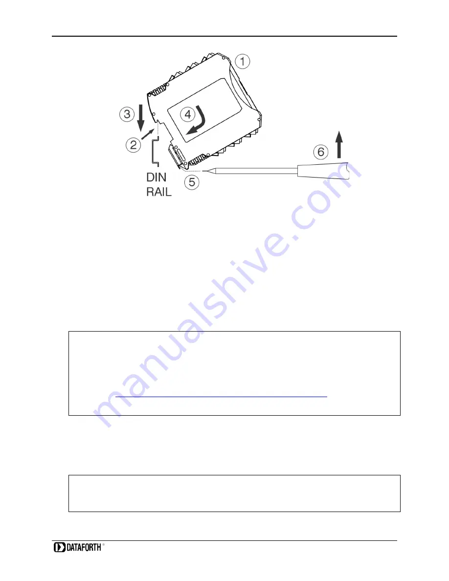
Figure 2: PWRM20-01 Installation and Removal from a DIN Rail


To remove a module:  
 

5.  Insert a flat blade screwdriver into the slot in the metal clip 

6.  Lift the screwdriver to pull back the clip and release the module from the rail 


4.2  Wiring to Phase Voltages and Phase Currents 

The  PWRM10-01 and  PWRM20-01  modules have  pluggable terminal  blocks  to connect to  phase 
voltages and phase currents. This allows modules to be easily added to or removed from a system. 
The modules are powered by the phase voltages and an external power supply is not required. 


DANGER 

 HAZARDOUS VOLTAGES


These wiring instructions are for use by qualified personnel only. 
Only licensed electricians or qualified personnel should install and maintain the modules and wiring. 
 
REFER  TO 

MA1068  PWRM10-01  &  PWRM20-01  Hardware  User  Manual

  FOR  DETAILS  ON 

WIRING TO PHASE VOLTAGE AND FOR SENSORS AND WIRING TO PHASE CURRENTS. 
 
 
PWRM10-01 and PWRM20-01 modules interface to phase currents with burden resistors, current 
transformers, or Rogowski Coils with 0.333VAC output at rated current. This low voltage interface is 
on the module top terminal blocks. 
 
PWRM10-01 and PWRM20-01 modules interface to phase voltages using the bottom terminal blocks.   


WARNING!


Mains voltages of 85VAC to 525VAC can be lethal! 


Summary of Contents for PWRM10-01

Page 1: ...PWRM10 01 PWRM20 01 IoT Energy Monitoring Modules MA1069 Quick Start Guide ...

Page 2: ...urate however Dataforth assumes no responsibility for possible inaccuracies or omissions Specifications are subject to change without notice The information tables diagrams and photographs contained herein are the property of Dataforth Corporation No part of this manual may be reproduced or distributed by any means electronic mechanical or otherwise for any purpose other than the purchaser s perso...

Page 3: ...n 8 4 3 1 Connecting a Module to a Computer Over a Network 8 4 3 2 Connecting a Module to a Computer Directly 8 4 3 3 Connecting a Module to a Tablet or Smartphone 8 5 0 Connecting to the Module 9 5 1 Downloading the PWRM Discovery Tool 9 5 2 Running the Discovery Tool 9 5 3 Selecting a Module and Connecting 11 6 0 Acquiring Data from the Module 12 6 1 Enter Sensing Device Parameters with Sensor C...

Page 4: ...ffects of noise transient power surges internal ground loops and other hazards present in industrial environments Dataforth spans the globe with more than 50 International Distributors and US Representative Companies Our customers benefit from a team of over 130 sales people highly trained in the application of precision products for industrial markets In addition we have a team of application eng...

Page 5: ...PWRM20 01 Connects to 3 Phase Systems 3 Wire Wye 4 Wire Wye and Delta Connects to Single Phase Systems Self Powered from any Phase A B or C 0 1 Phase Voltage Accuracy 0 1 Phase Current Accuracy Industrial Operating Temperature Range 40 C to 85 C 100ppm C Temperature Coefficient CE Compliant Industry Leading Functionality Internet of Things IoT Connectivity Simple Interface through a Web Browser Sm...

Page 6: ... inputs have an industry standard range of 0 333VAC full scale The modules are configurable to use an external shunt current transformer or Rogowski Coil to measure phase currents directly or non contact The PWRM10 01 and PWRM20 01 modules measure and report a wide range of electrical energy parameters which include but are not limited to RMS Voltages and Currents Phase Angles Line Periods Instant...

Page 7: ...ELECTRICAL SHOCK When installing and operating the PWRM10 01 and PWRM20 01 modules there is a potential shock hazard from dangerous high voltage Ensure systems are de energized before installing the product or removing the terminal blocks STEP 2 Connecting Communications to the Module o Download the PWRM Discovery Tool from the Dataforth website PWRM Software User Manual Download Center o Run the ...

Page 8: ...LECTRICAL SHOCK When installing and operating the PWRM10 01 and PWRM20 01 modules there is a potential shock hazard from dangerous high voltage Ensure systems are de energized before installing the product or removing the terminal blocks The PWRM10 01 and PWRM20 01 modules mount on 35mm DIN rails that are elevated or flush on panels They require no tools or hardware for insertion into a system and...

Page 9: ...tages and an external power supply is not required DANGER HAZARDOUS VOLTAGES These wiring instructions are for use by qualified personnel only Only licensed electricians or qualified personnel should install and maintain the modules and wiring REFER TO MA1068 PWRM10 01 PWRM20 01 Hardware User Manual FOR DETAILS ON WIRING TO PHASE VOLTAGE AND FOR SENSORS AND WIRING TO PHASE CURRENTS PWRM10 01 and P...

Page 10: ...MA1069 PWRM10 01 PWRM20 01 Quick Start Guide Page 6 of 16 Figure 3 PWRM10 01 3D View Figure 4 PWRM10 01 Wiring Diagram Terminal Block Positions ...

Page 11: ...MA1069 PWRM10 01 PWRM20 01 Quick Start Guide Page 7 of 15 Figure 5 PWRM20 01 3D View Figure 6 PWRM20 01 Wiring Diagram Terminal Block Positions ...

Page 12: ...e details Figure 7 PWRM10 01 Front Panel Figure 8 PWRM20 01 Front Panel 4 3 1 Connecting a Module to a Computer Over a Network Hardwire connect the PWRM10 01 or PWRM20 01 module to a network using a router or switch Connect a computer to the same network as the module using a hardwire connection through a router switch or wireless connection to a Wi Fi router or switch 4 3 2 Connecting a Module to...

Page 13: ...ne for 64 bit systems and one for 32 bit systems PWRM Discovery Tool 32 bit PWRM Discovery Tool 64 bit NOTE The PWRM Discovery Tool currently only runs on a Windows computer with operating system Win 7 or higher Future versions will run on tablet and smartphone devices 5 2 Running the Discovery Tool It may be necessary to modify corporate or local firewall settings for the tool to run Figure 9 Win...

Page 14: ... hover over a module Device Name in the list and right click to open the configure network menu Figure 11 Change IP Parameters Click Change IP Parameters then enter the desired static IP address parameters or select DHCP to allow a network controller to automatically assign an IP address Figure 12 Configure IP Parameters To push network configuration changes to the module press the OK button To ap...

Page 15: ...terface to a module can be opened from within the Discovery Tool Double click the Device Name or hover over the Device Name right click then select Open in Browser Figure 13 Open Web Interface in a Browser The Overview page will display after the connection is established Figure 14 Web Interface in a Browser ...

Page 16: ...nsors are configured First go to the Configuration Sensor page select devices used to measure phase currents and phase voltages and enter the device parameters Figure 15 Configuration Sensor Page Custom scaling parameters are available if required by an installation 6 2 Data Display in Tables Data is continuously collected from the module at the default poll rate of 1 second and posted to the appr...

Page 17: ...s The Data Charts page provides a graphical display of user selected readings from the module Charts will autoscale Figure 18 Data Chart Selection Select the charted data and number of data points to be displayed from the Select Category and History Capacity drop down menus Figure 19 Charted Data Selection ...

Page 18: ...9 PWRM10 01 PWRM20 01 Quick Start Guide Page 14 of 16 Figure 20 Data Chart Display 6 4 Data Logging The Data Data Logger page is where logging is configured and operated Figure 21 Data Data Logger Selection ...

Page 19: ...ll be opened This process will repeat until the Stop Logger button is pressed Data files will be downloaded upon completion or immediately by pressing the Download Now button The data filename is made up of the name specified and the date and time that the data was collected Figure 23 Logged Data File Format The web browser may post a pop up asking if downloading multiple files is to be allowed Lo...

Page 20: ...orization RMA instructions are found on the Dataforth website and can be accessed using this link RMA Instructions and Form The information provided herein is believed to be reliable however DATAFORTH assumes no responsibility for inaccuracies or omissions DATAFORTH assumes no responsibility for the use of this information and all use of such information shall be entirely at the user s own risk Ap...

Reviews: