N
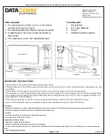
Figure 1:
Top view
- shows needed space between the drywall and the studs. The
power output plate should be centered between the studs.
Figure 2:
Using the template supplied (see page
3
of instruction sheet), trace the opening for both the top
and bottom plate. See Figure 1 before tracing your opening. Remember, the plates are designed to be
mounted centered between the studs. Using a drywall saw, cut a hole in the drywall the size of each template.
Figure 3:
Using a Philips screwdriver, secure male end of the in-wall connector to the female end that is attached
to the top plate using the included metal
strain relief
and screws.
Figure 4:
Run your low voltage cables and the included 14/2 with ground UL approved electrical building wire
from
the top opening in the wall through the bottom opening in the wall. You will need to fish the cables from the top
opening to the bottom opening.
Stop: Important:
Before installing the top power plate into the top template opening, make sure to pull your low
voltage cables through the low voltage cable opening at the back of the plate.
Figure 5:
After inserting your low voltage cables and the electrical building wire through the opening for the top
plate, install the top plate into the wall by inserting the electrical work box into the wall first (see Figure 5).
Slowly slide the top power plate into the opening. Swing the top of the plate into position until the entire plate is
flush against the wall.
Figure 6:
Using a Phillips screwdriver, tighten the screws with wings. These wings fasten tightly against the back
of the wall.
Note:
Do not overtighten screws.
Figure 7:
Pull cables out of bottom opening in the wall. Using a Phillips screwdriver, secure the male end of the in-
wall connector to the female end that is attached to the bottom plate
using the included metal strain relief and
screws
.
Figure 8:
Stop: Important:
Before installing the bottom recessed plate with inlet into the bottom template
opening, make sure to pull your low voltage cables through the low voltage cable opening in the back of the plate.
After you have pulled your low voltage and audio/video cables through the bottom power input plate, insert the
side of the plate with the electrical work box into the wall. (see Figure 8). Swing the right side of the plate into
position until the entire plate is flush against the wall. Now tighten the screws with wings. These wings fasten
tightly against the back of the wall. Note: Do not overtighten screws.
Figure 9:
Now hang your flat panel TV on the mounting bracket (not included) and plug your TV into the top power
output plate. Then plug your power cord set into the bottom power input plate. Complete installation by plugging
the male end of the power cord set into the nearby wall receptacle.
Page 2 of 3
11/05/2018


