CP80 and CP80 Plus Service Manual
6-51
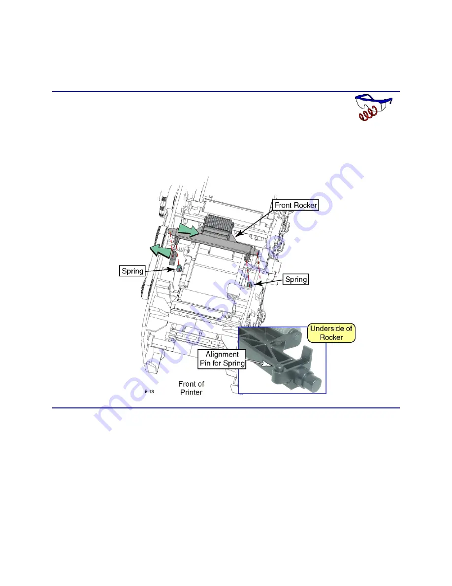
Front Rocker Assembly
When replacing the rocker assembly, it is a good idea to replace the springs as
well.
Removal Procedure
1.
Turn off the printer and unplug the power cord.
2.
Remove the ribbon cartridge and cleaning roller.
3.
Push the rocker assembly one direction and the rocker mounting tab in the
opposite direction, and pull up on the rocker. Be careful not to lose the
springs.
Replacement Note
Make sure the springs are seated in the pockets of the transport chassis, and on
the alignment pins of the rocker assembly.
Summary of Contents for CP80 Plus
Page 1: ...Datacard CP80 and CP80 Plus Card Printers Service Manual May 2007 Part No 539490 002 Rev C ...
Page 14: ...1 4 Introduction ...
Page 17: ...CP80 and CP80 Plus Service Manual 2 3 Print Engine Functional Block Diagram ...
Page 18: ...2 4 Theory of Operation Laminator Functional Block Diagram ...
Page 22: ...2 8 Theory of Operation LCD Service Mode Menu Diagram ...
Page 52: ...2 38 Theory of Operation ...
Page 158: ...6 6 Removal and Replacement Print Engine Front Wire Routing Diagram ...
Page 159: ...CP80 and CP80 Plus Service Manual 6 7 Print Engine Duplex and Printhead Wire Routing Diagram ...
Page 160: ...6 8 Removal and Replacement Laminator Front Wire Routing Diagram ...
Page 161: ...CP80 and CP80 Plus Service Manual 6 9 Laminator Rear Wire Routing Diagram ...
Page 162: ...6 10 Removal and Replacement Power Supply Wire Routing Diagram ...
Page 163: ...CP80 and CP80 Plus Service Manual 6 11 Print Engine Cable Connection Diagram ...
Page 164: ...6 12 Removal and Replacement Laminator Cable Connection Diagram ...


