background image

Alltech 3300 ELSD

4 Using the control module

4 Using the control module

New

Acquisition

tab is created in the

Method Setup

dialog. If there are any

other detectors configured on the instrument, then the

Alltech 3300 ELSD

detector can be accessed by switching to the desired signal in the

Select

Detector

section on the top of the dialog.

- 6 -

Summary of Contents for Alltech 3300 ELSD

Page 1: ...trols Alltech 3300 ELSD DET ENG Code Rev M151 70A Date 1 10 2017 Phone 420 251 013 400 DataApex Ltd Fax 420 251 013 401 Petrzilkova 2583 13 clarity dataapex com 158 00 Prague 5 www dataapex com The Czech Republic ...

Page 2: ...demarks of DataApex Ltd Microsoft and WindowsTM are trademarks of Microsoft Corporation DataApex reserves the right to make changes to manuals without prior notice Updated manuals can be downloaded from www dataapex com Author MP ...

Page 3: ...ng 3 3 2 Clarity Configuration 4 4 Using the control module 6 4 1 Alltech 3300 ELSD Setup 7 4 2 Digital Outputs of Alltech 3300 ELSD 8 4 3 Method Setup Acquisition 9 4 3 1 Method Setup Acquisition Settings 10 4 3 2 Method Setup Acquisition Time Table 12 4 4 Method Setup Advanced 13 4 5 Device Monitor 14 5 Report Setup 15 6 Troubleshooting 16 i ...

Page 4: ...K1 capitals indicates the name of the file and or directory ACTIVE capitalitalics marks the state of the station or its part The bold text is sometimes also used for important parts of the text and the name of the Clarity station Moreover some sections are written in format other than normal text These sections are formatted as follows Note Notifies the reader of relevant information Caution Warns...

Page 5: ... enables direct control of the instrument over Ethernet LAN connection Fig 1 Alltech 3300 ELSD detector Direct control means that the detector can be completely controlled from the Clarity environment including the digital data acquisition That way no A D converter is needed Instrument method controlling the analysis conditions will be saved in the measured chromatograms 1 ...

Page 6: ...p n A24 Caution Minimal firmware version required for 3300 ELSD is 1 0 32 l Crossed LAN cable p n SK08 l Both PC and detector connected to the same Ethernet network Note Cables are not part of Clarity Control Module It is strongly recommended to order required cables together with the Control Module 2 ...

Page 7: ...t of modern switches are able to automatically adapt to both types of cable For connecting the detector with other devices using synchronization inputs and outputs there is 14 Pin connector available on the backside of the detector Pins 1 2 are Start input used for starting the detector by external device pins 9 10 accommodate External Output suitable for controlling some other device For detailed...

Page 8: ... on the desktop l Invoke the System Configuration dialog accessible from the Clarity window using the System Configuration command l Press the Add button see 3 2 on pg 4 to invoke the Available Control Modules dialog l You can specify the searching filter to simplify the finding of the driver l Select the Alltech 3300 ELSD and press the Add button 4 ...

Page 9: ...al name l Press the OK button The Alltech 3300 ELSD will appear in the Setup Control Modules list of the System Configuration dialog l Drag and drop the Alltech 3300 ELSD icon from the Setup Control Modules list on the left side of the System Configuration dialog to the desired Instrument tab on the right side or use the button to do so Note The configuration dialog of the Alltech 3300 ELSD detect...

Page 10: ...dule New Acquisition tab is created in the Method Setup dialog If there are any other detectors configured on the instrument then the Alltech 3300 ELSD detector can be accessed by switching to the desired signal in the Select Detector section on the top of the dialog 6 ...

Page 11: ...sing the previously set IP Address Obtained data about the detector are then displayed in the dialog Signal 1 Name Enables to set the relevant detector name Digital Output Names Displays the Digital Output Names dialog which enables to set the custom labels of Alltech 3300 ELSD digital outputs The custom names are displayed in the Device Monitor window described in the chapter Device Monitor on pg...

Page 12: ...SD 4 Using the control module 4 2 Digital Outputs of Alltech 3300 ELSD Fig 6 Digital Outputs of Alltech 3300 ELSD Serves for setting the initial and actual state of the Alltech 3300 ELSD detector s auxiliary output 8 ...

Page 13: ... 3300 ELSD detector prior to each injection in the ACTIVE sequence and may be sent there manually by using the Send Method button in the lower part of this tab or in the Single Analysis dialog Some analysis parameters cannot be modified neither from Clarity nor directly on the Alltech 3300 ELSD detector These parameters are not changed when sending the method to the detector Setting of the acquisi...

Page 14: ...Drift Tube Turn on the heater of the upper part of drift tube Heater Optics Block Turn on the heater of the optics block Gas Flow Turn on the flow of carrier gas Laser Turns on the laser Gain Sets the gain of the detector Shutdown Sets the behavior of the detector after the analysis is completed Keep State Detector keeps the ON state Set Off after analysis Set the detector OFF after an analysis is...

Page 15: ...n 0 3 ml min of the value set in the Gas Flow Rate field When any of the two parameters exceeds the limits the timer set in the Equilibry Time field resets Lower section of the Method Setup Acquisition dialog In the right section on all Method Setup Acquisition sub tabs for Alltech 3300 ELSD detector new button emerges Det Status After pressing the Det Status button the Hardware Configuration dial...

Page 16: ...od Setup Acquisition Time Table This sub tab serves for time program to change operating parameters during run Available Event Types are Autozero setting the zero for detector output and Gain setting the gain of the detector Fig 9 Method Setup Time Table 12 ...

Page 17: ...mmand the Method Setup Advanced dialog will open The tab is common to all signals while performing multidetector measurement Fig 10 Method Setup Acquisition Advanced Subtraction Set the chromatogram for subtraction from the measured signal Column Calculations Set the parameters of the column Auxiliary Signal table Set which auxiliary signals will be stored in the chromatogram file 13 ...

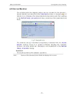
Page 18: ... settings in the Method Setup Acquisition window as well as other parameters set there Fig 11 Device Monitor The detector can be monitored and partially controlled from the Device Monitor window There is a control command allowing the AutoZero function all other fields are informative and described in the Method Setup Acquisition dialog Auto Zero This button performs the autozero operation Note Va...

Page 19: ... of the detector settings accessible on the Method Setup Acquisition tab for the given signal are reported To do so the Instrument Control parameter on the Method tab of the Report Setup dialog must be checked Fig 12 Print Preview of the Report Setup 15 ...

Page 20: ... should be edited or added TCP_IP 192 168 0 100 79 echo on textmode on filename Alltech3300ELSD_ D txt reset off Note Instead of 192 168 0 100 79 type correct IP address and port used for communication with the Alltech 3300 ELSD detector This port number is displayed when the Det Status button in the Method Setup Acquisition dialog is invoked Note D or d in the filename parameter means that the lo...

Reviews: