13
DT-NTSC-32 Manual
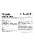
Figure-3.1
1. To refresh the input program information
2. To refresh the output program information
3. Select one input program first and click this button to transfer the selected program
to the right box to output.
4. Similarly, users can cancel the multiplexed programs from the right box.
5. To select all the input programs
6. To select all the output programs
7. To parse programs time limitation of parsing input programs
1
2
3
4
5
6
7