Chapter 5
88
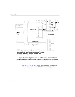
Figure 40: Cascading Counters on an STP268 Screw Terminal Panel
(Shown for Event Counting Using Counters 0 and 1 and External Gate 0)
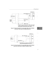
, and
show examples of connecting
event counting signals to the STP268-EC screw terminal panel.
STP268 Panel
TB54
Signal Source
User Clock Input 0
TB57
TB56
Digital Ground
Gate 0
External
Gating
Switch
TB55
TB58
User
Counter
Output 0
User Clock
Input 1
TB60
Gate 1
Note that the signals shown for the STP268 screw terminal panel
correspond to connector J1.
Note that you can internally cascade counters using software; if you
internally cascade the counters, you do not have to make the
external cascading connections. Note also that this example shows
the use of an external gate; however, this connection is not required.
Summary of Contents for DT3010 Series
Page 1: ...R DT3010 Series UM 16868 C Getting Started Manual ...
Page 22: ...Chapter 2 12 ...
Page 36: ...Chapter 3 26 ...
Page 114: ...Chapter 5 104 ...
Page 136: ...Appendix A 126 ...
Page 142: ...Index 132 ...


