background image

Chapter 4

62

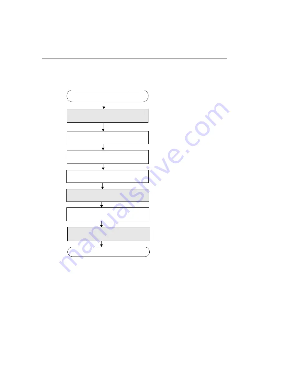
Passthru without Overlays

Set the standard controls for the input 

source (see 

page 68

).

Choose an input source with 
OlFgSetInputVideoSource.

Open the device and get the device ID 

with OlImgOpenDevice.

Go to the next page.

Set the color controls for the 

input source (see 

page 69

).

Only channel 0, the default, is 
supported.

Set the timeout period with 

OlImgSetTimeoutPeriod.

Scale passthru image with

DtColorHardwareScaling.

Start the passthru operation

(see 

page 74

).

Acquire a single image for processing

(see 

page 75

).

Specify the scaling factors for the input 
channel as a percentage of the original size 
(default = 100).

Summary of Contents for 18729

Page 1: ...zed and idle equipment along with credit for buybacks and trade ins Custom engineering so your equipment works exactly as you specify Critical and expedited services Leasing Rentals Demos In stock Ready to ship TAR certified secure asset solutions Expert team I Trust guarantee I 100 satisfaction All trademarks brand names and brands appearing herein are the property of their respective owners Find...

Page 2: ...DT3120 UM 18109 E User s Manual ...

Page 3: ...n or otherwise under any patent rights of Data Translation Inc Use duplication or disclosure by the United States Government is subject to restrictions as set forth in subparagraph c 1 ii of the Rights in Technical Data and Computer software clause at 48 C F R 252 227 7013 or in subparagraph c 2 of the Commercial computer Software Registered Rights clause at 48 C F R 52 227 19 as applicable Data T...

Page 4: ...es or modifications to this equipment not expressly approved by Data Translation could void your authority to operate the equipment under Part 15 of the FCC Rules Note This product was FCC Certified under test conditions that included use of shielded cables and connectors between system components It is important that you use shielded cables and connectors to reduce the possibility of causing inte...

Page 5: ......

Page 6: ...Overview 1 Features 2 Supported Software 3 Chapter 2 Principles of Operation 5 Video Input Signals 7 Video Signal Types 7 Videos Input Channels 8 Color Intensity 9 Pixel Clock 9 Triggers 10 Sync Signals 11 Video Area 12 Active Video Area 12 Horizontal Video Signal 13 Vertical Video Signal 14 Frame Region of Interest 15 Frame Size 15 Types of Frames 17 Scaling Frames 18 Frame Storage Mode 19 ...

Page 7: ... 29 DT3120 Device Driver Capabilities 30 Initialized Control Values 52 Chapter 4 Programming Flowcharts 55 Single Frame Acquisition 57 Multiple Frame Acquisition 60 Passthru without Overlays 62 Passthru with Overlays 64 Chapter 5 Troubleshooting 79 General Checklist 80 Service and Support 84 Telephone Technical Support 84 E Mail and Fax Support 87 World Wide Web 87 If Your Board Needs Factory Serv...

Page 8: ...ration 95 Uninstalling the Device Driver 96 Windows 2000 Procedures 97 Adding a Board to the Device Driver Configuration 97 Modifying a Board in the Device Driver Configuration 98 Uninstalling the Device Driver 98 Windows XP Procedures 100 Adding a Board to the Device Driver Configuration 100 Modifying a Board in the Device Driver Configuration 101 Uninstalling the Device Driver 101 Index 103 ...

Page 9: ...Contents viii ...

Page 10: ... you are writing application programs using the device driver and the Frame Grabber SDK it is also assumed that you are familiar with the Microsoft Windows 98 Windows Me Millennium Edition Windows 2000 or Windows XP operating system and with the Microsoft C compiler What You Should Learn from this Manual This manual provides detailed information about the features of the DT3120 board and the DT312...

Page 11: ...cifications lists the specifications of the boards Appendix B Modifying the Device Driver describes how to add modify and remove boards from the device driver and how to uninstall the device driver if necessary An index complete this manual Conventions Used in this Manual The following conventions are used in this manual Notes provide useful information that requires special emphasis cautions prov...

Page 12: ... you can use to write image acquisition application software DT Active Open Layers User s Manual UM 17325 available from Data Translation describes DT Active Open Layers an ActiveX control which allows you to use Data Translation PCI frame grabber boards within graphical programming environments such as Microsoft Visual Basic and Visual C GLOBAL LAB Image 2 User s Manual UM 17790 and GLOBAL LAB Im...

Page 13: ...liffs NJ Prentice Hall 1987 Explains major image processing concepts and mathematical concepts involved in digital image manipulation Cunningham John E Cable TV 2nd ed Indianapolis Howard W Sams Company Inc 1987 Provides the basics of cable television Foley J D and A Van Dam Fundamentals of Interactive Computer Graphics Addison Wesley Reading MA 1984 Provides information on geometric functions Fri...

Page 14: ...vers television and video basics Lindley Craig Practical Image Processing in C Somerset NJ John Wiley Sons Inc 1991 Explains basic image processing techniques using C provides many programming examples covers TIFF and PICT file formats and describes how to map images into VGA memory space Luther Arch C Digital Video in the PC Environment New York McGraw Hill 1991 Explains Digital Video Interactive...

Page 15: ... and Avinash C Kak Digital Picture Processing New York Academic Press Inc 1990 Describes image processing techniques and concepts Russ John C Computer Assisted Microscopy The Measurement and Analysis of Images New York Plenum Press Serra J Image Analysis and Mathematical Morphology London Academic Press Ltd 1982 Provides information on morphological processing Smith C Cecil Mastering Television Te...

Page 16: ...here to Get Help Should you run into problems installing or using a DT3120 board the Data Translation Technical Support Department is available to provide technical assistance Refer to Chapter 5 for more information If you are outside the United States or Canada call your local distributor whose number is listed in your Data Translation product handbook ...

Page 17: ...About this Manual xvi ...

Page 18: ...1 1 Overview Features 2 Supported Software 3 ...

Page 19: ...Operates as PCI bus masters on half size board Supports the scatter gather memory capability using the PCI interface chip Supports one monochrome or composite video input which uses the NTSC RS 170 or PAL CCIR video format or one S video signal which uses the Y C video format Accepts a software or external trigger Acquires single or multiple fields and or frames synchronously or asynchronously Sto...

Page 20: ...Streamline This package is shipped with the board if you purchased the SCI PAK package This package allows you to create scientific applications using object oriented image processing tools 32 Bit Frame Grabber SDK Use this software package provided on the Imaging OMNI CD if you want to develop your own application software for the DT3120 board using the Microsoft C compiler in Windows 98 Windows ...

Page 21: ...Chapter 1 4 Refer to the Data Translation catalog for information on additional software packages available for the DT3120 board ...

Page 22: ...5 2 Principles of Operation Video Input Signals 7 Sync Signals 11 Video Area 12 Passthru Operations 22 Acquisition Operations 26 ...

Page 23: ...o the block diagram of the DT3120 board shown in Figure 1 Bold signal names indicate signals you can access Figure 1 DT3120 Block Diagram Primary PCI Bus PCI Interface Video Input ADC Programmable Image Scaling Programmable Image Cropping FIFO External Trigger ...

Page 24: ...s 8 bit grayscale values Composite CVBS The Color Video Broadcast Standard where both luminance and chrominance information is encoded on a single composite video signal The signal passes through high and low pass filters on the board to separate the chrominance and luminance signals The decoded signals are represented as 8 bit data S Video This signal contains both luminance and chrominance infor...

Page 25: ...chrome video signal In this format the video input is a single analog signal A video frame is displayed as 768 x 576 lines The Y C format is supported for an S video input In this format the video input is provided as two separate analog signals The Y signal contains luminance information the gray scale portion of the color image The C signal contains chrominance information the color portion of t...

Page 26: ... an image For example if a particular pixel has a value of 0 for green but a value of 511 for blue then the pixel is said to be saturated in blue Values range from 0 to 511 in increments of 1 the nominal value is 180 U Saturation The purity of the green and red primary colors in an image For example if a particular pixel has a value of 0 for green but a value of 511 for red then the pixel is said ...

Page 27: ...vents By default the external trigger is disabled Through software you can enable the external trigger You program the trigger source for the acquisition using software You can specify whether to start image acquisition when the board detects either a low to high edge rising edge transition or a high to low edge falling edge transition The incoming external trigger is forwarded to the device drive...

Page 28: ...vertical sync signals The board determines this information as well as the odd and even fields from the video input signal being digitized Horizontal sync pulses are asserted low for 4 µs typically Vertical sync pulses are asserted low for 230 µs typically The odd field indication changes state on the falling edge of the vertical sync signal ...

Page 29: ...els per line as follows You can calculate the total lines per field as follows Active Video Area The active video area floats in the total video area The active video area is defined as that part of the incoming signal that contains valid video data not blanking or sync information Therefore the active video area consists of the visible portion of those lines containing visible pixel data Its top ...

Page 30: ...nal A horizontal line of video is identified by the falling edge of the horizontal sync and a field is composed of a collection of horizontal lines defined by the active line count Pixel measurements are relative to the horizontal reference point which is defined as the beginning of the horizontal sync The horizontal video signal settings are fixed and cannot be programmed Front Porch Horizontal S...

Page 31: ...tive video area For information about the frame refer to page 15 Figure 3 Vertical Video Signal Line measurements are relative to the vertical reference point which is defined as the beginning of the vertical sync Lines themselves are measured in terms of pixels The vertical video signal settings are fixed Blanking 0 1 2 3 n 1 Vertical Reference Point First Active Line Frame Top Frame Height Activ...

Page 32: ... Frame type Scaling frames and Frame storage modes Frame Size The top of the frame is the first line of video relative to the active video area The left side of the frame is the first pixel of video relative to the active video area The width of the frame is the number of pixels per line of video The height of the frame is the number of lines per field Table 1 shows the settings you can program on...

Page 33: ... 763 pixels 60 Hz 0 to 635 pixels 0 Frame Width The number of pixels per line of video to digitize 50 Hz 1 to 768 pixels 60 Hz 1 to 640 pixels 50 Hz 768 60 Hz 640 Frame Top The first line of the region of interest relative to the first active line to digitize 50 Hz 0 to 575 lines 60 Hz 0 to 479 linesa 0 Frame Height The number of lines per frame of video to digitize 50 Hz 1 to 576 lines 60 Hz 1 to...

Page 34: ...ired to create the complete frame The even field contains lines 0 2 4 and so on the odd field contains lines 1 3 5 and so on Using software you can select one of the following types of frame acquisitions Interlaced frames starting on the next even field the default Interlaced frames starting on the next odd field First Active Pixel First Active Line Active Video Area Frame Active Line Count Total ...

Page 35: ... the size of an image The number of lines per frame in the scaled image can range from 1 to 480 for 60 Hz image formats or from 1 to 576 for 50 Hz image formats in increments of 1 The number of pixels per line in the scaled image can range from 4 to 640 for 60 Hz image formats or from 4 to 768 for 50 Hz image formats in increments of 4 Using software you provide the scale factor for the horizontal...

Page 36: ... as shown in Figure 5 RGB16 16 bits per pixel as shown in Figure 6 RGB24 24 bits per pixel as shown in Figure 7 and RGB 32 bits per pixel as shown in Figure 8 and YUYV422 16 bits per pixel as shown in Figure 9 Figure 5 Monochrome Mode 8 Bit Data Format DWORD Format M1M2M3M4 M5M6M7M8 Address 0 4 Byte Format Address 0 1 2 3 4 5 6 7 M1 M2 M3 M4 M5 M6 M7 M8 ...

Page 37: ...Format Figure 7 RGB 24 Bit Color Data Format Byte Format RGB1 RGB3 Address 0 1 2 3 4 5 6 7 RGB2 RGB4 DWORD Format Address 0 4 RGB1 RGB3 RGB2 RGB4 Byte Format Address 0 1 2 3 4 5 6 7 R1 G1 B1 R2 G2 B2 R3 G3 DWORD Format Address 0 4 R1G1B1R2 G2B2R3B3 ...

Page 38: ... Data Format Figure 9 YUYV422 16 Bit Data Format Byte Format Address 0 1 2 3 4 5 6 7 R1 G1 B1 X1 R2 G2 B2 X2 DWORD Format Address 0 4 R1G1B1X1 R2G2B2X1 Byte Format Y0U0Y1V0 Address 0 1 2 3 4 5 6 7 DWORD Format Address 0 4 YUYV0 YUYV2 YUYV1 YUYV3 Y2U1Y3V1 Y4U2Y5V2 Y6U3Y7V3 ...

Page 39: ...ory if desired This operation is called continuous acquire passthru mode This section describes the following aspects of passthru Passthru modes Source origin Passthru scaling and Overlays Passthru Modes The DT3120 board supports bitmap passthru mode and continuous acquire passthru mode This section describes these modes Bitmap Passthru Mode The DT3120 board supports asynchronous bitmap passthru m...

Page 40: ...hru mode Since it is asynchronous the operation starts but gives control to you immediately allowing you to perform other operations while data is acquired and or displayed Using software you can set up the continuous acquire passthru operation so that data is continuously stored and displayed or continuously stored but not displayed If you want to display data in continuous acquire passthru mode ...

Page 41: ...d to scale passthru images The number of lines per frame in the scaled image can range from 1 to 480 for 60 Hz image formats or from 1 to 576 for 50 Hz image formats in increments of 1 The number of pixels per line in the scaled image can range from 4 to 640 for 60 Hz image formats or from 4 to 768 for 50 Hz image formats in increments of 4 Using software you provide the scale factor for the horiz...

Page 42: ... 2 2 Overlays You can add overlays to the display using software during passthru operations Overlays allow you to place an image on top of another image that was captured using passthru Note Overlays require Direct Draw Interface DDI support ...

Page 43: ...you to perform other operations while data is acquired Using the DT3120 you can acquire a single full frame a single field subframe multiple full frames or multiple fields Data is stored to an area in system memory that is allocated by the DT3120 Device Driver called device memory Table 2 lists the memory size that is used for each image format and image type supported Table 2 Memory Used Video Fo...

Page 44: ...DT3120 to transfer an unlimited number of consecutive frames across the bus in real time You can acquire consecutive images up to the capacity of available system RAM Acting as a PCI bus master the board sends pixel data over the PCI bus directly using burst transfer rates up to 30 frames s for 60 Hz image formats and 25 frames s for 50 Hz image formats when used with a 16 bit or 32 bit color disp...

Page 45: ...Chapter 2 28 ...

Page 46: ...29 3 Supported Device Driver Capabilities DT3120 Device Driver Capabilities 30 Initialized Control Values 52 ...

Page 47: ...ity The tables in this chapter list the capabilities supported by the DT3120 board and the information needed to query the board The left column of the tables lists the capabilities along with the query key control used for the listed function The query s possible returned flags if any are indented under the key along with a description The right column indicates whether the DT3120 board support t...

Page 48: ... use the query functions to determine that the capability is supported by the installed board prior to execution For more information refer to the description of SDK functions in the Frame Grabber SDK online help Overlay page 47 Memory page 48 Acquisition page 49 Digital I O page 51 For capabilities that apply to Refer to the table starting on ...

Page 49: ...DEVICE_TYPE Monochrome Frame Grabber OLC_IMG_DEV_MONO_FRAME_GRABBER Color Frame Grabber OLC_IMG_DEV_COLOR_FRAME_GRABBER Yes Yes Sections Supported OLC_IMG_DC_SECTIONS Supports Input Operations OLC_FG_SECTION_INPUT Supports Camera Control Operations OLC_FG_SECTION_CAMCTL Supports Management of Device Memory OLC_FG_SECTION_MEMORY Supports Linear Memory Operations OLC_FG_SECTION_LINEAR Supports passt...

Page 50: ...pports Hardware Scaling COLOR_INTERFACE_HARDWARE_SCALING Supports Digital I O COLOR_INTERFACE_DIGITAL_IO Supports Draw Acquired Frame COLOR_INTERFACE_DRAW_ACQUIRED_FRAME Supports Sync Master Mode COLOR_INTERFACE_SYNC_MASTER_MODE Supports Extracting RGB Frames COLOR_INTERFACE_EXTRACT_FRAME Supports Drawing Extracted Data COLOR_INTERFACE_DRAW_BUFFER True True True True False True False False False T...

Page 51: ...pled no Input Filter OLC_FG_FILT_AC_NONE AC Coupled 50 Hz Input Filter OLC_FG_FILT_AC_50 AC Coupled 60 Hz Input Filter OLC_FG_FILT_AC_60 DC Coupled no Input Filter OLC_FG_FILT_DC_NONE N A Supports Programmable A D OLC_FG_IC_DOES_PROG_A2D No Supports Programmable A D Query OLC_FG_IC_DOES_QUERY_PROG_A2D No Voltage Range of Black Level in µV OLC_FG_IC_BLACK_LEVEL_LIMITS N A Voltage Range of White Lev...

Page 52: ...Trigger Types OLC_FG_TRIGGER_TYPE_LIMITS Supports Externally Triggered Acquisition OLC_FG_TRIG_EXTERNAL_LINE Yes Multiple Trigger Types OLC_FG_IC_MULT_TRIGGER_TYPE_LIMITS Supports Externally Triggered Acquisition OLC_FG_TRIG_EXTERNAL_LINE Yes Multiple Trigger Modes OLC_FG_IC_MULT_TRIGGER_MODE_LIMITS Trigger Starts Multiple Frame Acquisition OLC_FG_MODE_START Trigger Starts Each Frame Acquisition O...

Page 53: ...LUT_COUNT 0 Maximum Index Allowed in each ILUT OLC_FG_IC_MAX_ILUT_INDEX N A Maximum Value Allowed in each ILUT OLC_FG_IC_MAX_ILUT_VALUE N A DtColorSignalType Signal Type in the SDK Extensions OLT_SIGNAL_TYPE Supports Monochrome Signal Type OLC_MONO_SIGNAL Supports Y C Signal Type Luminance Chrominance OLC_YC_SIGNAL Support Composite Signal Type OLC_COMPOSITE_SIGNAL Supports RGB Signal OLC_RGB_SIGN...

Page 54: ..._SET_CONTRAST V Saturation Values OLC_SET_V_SAT U Saturation Values OLC_SET_U_SAT Hue Values OLC_SET_HUE min 0 max 255 nominal 128 granularity 1 min 0 max 511 nominal 216 granularity 1 min 0 max 511 nominal 180 granularity 1 min 0 max 511 nominal 254 granularity 1 min 0 max 255 nominal 128 granularity 1 Table 4 Input Signal Capabilities for the DT3120 Device Driver cont Capability DT3120 Support ...

Page 55: ...EF Green Offset OLC_SET_GREEN_OFFSET Blue Reference OLC_SET_BLUE_REF Blue Offset OLC_SET_BLUE_OFFSET N A N A N A N A N A N A N A N A N A Table 5 Sync Signal Capabilities for the DT3120 Device Driver Capability DT3120 Support OlFgQueryInputCaps Supports Input Video Selection OLC_FG_IC_DOES_VIDEO_SELECT Yes Supports Input Video Selection Query OLC_FG_IC_DOES_QUERY_VIDEO_SELECT Yes Table 4 Input Sign...

Page 56: ... Composite Sync Threshold Limits in mV OLC_FG_IC_CSYNC_THRESH_LIST_LIMITS N A Composite Sync Threshold List OLC_FG_IC_CSYNC_THRESH_LIST N A Supports Sync Sentinel OLC_FG_IC_DOES_SYNC_SENTINEL No Supports Sync Sentinel Query OLC_FG_IC_DOES_QUERY_SYNC_SENTINEL Yes Sync Sentinel Types OLC_FG_IC_SYNC_SENTINEL_TYPE_LIMITS Supports Fixed Sync Sentinel OLC_FG_SYNC_SENTINEL_FIXED Supports Variable Sync Se...

Page 57: ...O Yes Range of Back Porch Start Position OLC_FG_IC_BACK_PORCH_START_LIMITS min 0 max 0 nominal 0 granularity 0 Range of Clamp Start Position OLC_FG_IC_CLAMP_START_LIMITS min 0 max 0 nominal 0 granularity 0 Range of Clamp End Position OLC_FG_IC_CLAMP_END_LIMITS min 0 max 0 nominal 0 granularity 0 Range of Total Pixels Per Line Control OLC_FG_IC_TOTAL_PIX_PER_LINE_LIMITS min 50 Hz 1135 60 Hz 910 max...

Page 58: ... Pixels Count OLC_FG_IC_ACTIVE_WIDTH_LIMITS min 50 Hz 768 60 Hz 640 max 50 Hz 768 60 Hz 640 nominal 50 Hz 768 60 Hz 640 granularity 0 Range of Total Lines per Field Control OLC_FG_IC_TOTAL_LINES_PER_FLD_LIMITS min 50 Hz 312 60 Hz 262 max 50 Hz 312 60 Hz 262 nominal 50 Hz 312 60 Hz 262 granularity 0 Table 6 Active Video Area Capabilities for the DT3120 Device Driver cont Capability DT3120 Support ...

Page 59: ...88 60 Hz 240 max 50 Hz 288 60 Hz 240 nominal 50 Hz 288 60 Hz 240 granularity 0 Table 7 Frame Capabilities for the DT3120 Device Driver Capability DT3120 Support OlFgQueryInputCaps Supports Frame Selection OLC_FG_IC_DOES_FRAME_SELECT Yes Supports Frame Selection Query OLC_FG_IC_DOES_QUERY_FRAME_SELECT Yes Table 6 Active Video Area Capabilities for the DT3120 Device Driver cont Capability DT3120 Sup...

Page 60: ...EFT_LIMITS min 0 max 50 Hz 763 60 Hz 635 nominal 0 granularity 1 Range of Frame Height Control OLC_FG_IC_FRAME_HEIGHT_LIMITS min 1 max 50 Hz 576 60 Hz 480 nominal 50 Hz 576 60 Hz 480 granularity 1 Range of Frame Width Control OLC_FG_IC_FRAME_WIDTH_LIMITS min 1 max 50 Hz 768 60 Hz 640 nominal 50 Hz 768 60 Hz 640 granularity 1 Table 7 Frame Capabilities for the DT3120 Device Driver cont Capability D...

Page 61: ...Field OLC_FG_FRM_IL_FRAME_ODD Acquire Interlaced Frame Starting on Next Field OLC_FG_FRM_IL_FRAME_NEXT Acquire the Even Field OLC_FG_FRM_FIELD_EVEN Acquire the Odd Field OLC_FG_FRM_FIELD_ODD Acquire the Next Field OLC_FG_FRM_FIELD_NEXT Acquire the Next Noninterlaced Frame OLC_FG_FRM_NON_INTERLACED Yes Yes Yes Yes Yes Yes No Maximum Number of Pixels in Frame OLC_FG_IC_MAX_FRAME_SIZE 50 Hz 442368 60...

Page 62: ...1 min 1 max 100 nominal 100 granularity 1 DtColorStorageMode Storage Mode in the SDK Extensions OLT_IMAGE_MODE Supports Monochrome Mode OLC_IMAGE_MONO Supports YUV Mode OLC_IMAGE_YUV Supports RGB OLC_IMAGE_RGB Supports RGB24 OLC_IMAGE_RGB_24 Supports RGB16 OLC_IMAGE_RGB_16 Supports RGB15 OLC_IMAGE_RGB_15 Supports YUYV422 OLC_IMAGE_YUYV_422 Yes No Yes Yes Yes No Yes Table 7 Frame Capabilities for t...

Page 63: ...RU_ASYNC_BITMAP Supports Sync Bitmap OLC_FG_PASSTHRU_SYNC_BITMAP Supports Continuous Acquire OLC_FG_PASSTHRU_ASYNC_BITMAP_EXTENDED No No Yes No Yes Source Origin OLC_FG_PC_DOES_SOURCE_ORIGIN Available Range for the X Value of the Source Origin OLC_FG_PC_SRC_ORIGIN_X_LIMITS No N A Source Origin Available Range for the Y value of the Source Origin OLC_FG_PC_SRC_ORIGIN_Y_LIMITS N A Passthru Scaling O...

Page 64: ...s a With the DT3120 use the DtColorHardwareScaling function to perform passthru scaling Table 9 Overlay Capabilities for the DT3120 Device Driver Capability DT3120 Support OlFgQueryDDICaps Passthru with DDI OLC_FG_DDI_FAST_PASSTHRU No Overlay support OLC_FG_DDI_OVERLAYS Yes Translucent overlay capability OLC_FG_DDI_TRANSLUCENT_OVERLAYS No Color overlay capability OLC_FG_DDI_COLOR_OVERLAY Yes Multi...

Page 65: ...bility DT3120 Support OlFgQueryMemoryCaps Memory Types OLC_FG_MC_MEMORY_TYPES Volatile Memory OLC_FG_MEM_VOLATILE Nonvolatile Memory OLC_FG_MEM_NON_VOLATILE Yes No Number of Volatile Buffer Handles OLC_FG_MC_VOL_COUNT 1a a You can allocate as many frames as the system memory allows using OlFgAllocateBuiltInFrame Number of Nonvolatile Buffer Handles OLC_FG_MC_NONVOL_COUNT N A Table 9 Overlay Capabi...

Page 66: ..._TO_FIT Single Frame to Device sync Supports Full Frame Acquisition OLC_FG_ACQ_FRAME Supports Subframe Acquisition OLC_FG_ACQ_SUBFRAME Supports Frame to Fit Acquisition OLC_FG_ACQ_FRAME_TO_FIT Single Frame to Host async Supports Full Frame Acquisition OLC_FG_ACQ_FRAME Supports Subframe Acquisition OLC_FG_ACQ_SUBFRAME Supports Frame to Fit Acquisition OLC_FG_ACQ_FRAME_TO_FIT Single Frame to Device ...

Page 67: ...FRAME_TO_FIT Multiple Frames to Host async Supports Full Frame Acquisition OLC_FG_ACQ_FRAME Supports Subframe Acquisition OLC_FG_ACQ_SUBFRAME Supports Frame to Fit Acquisition OLC_FG_ACQ_FRAME_TO_FIT Multiple Frames to Device async Supports Full Frame Acquisition OLC_FG_ACQ_FRAME Supports Subframe Acquisition OLC_FG_ACQ_SUBFRAME Supports Frame to Fit Acquisition OLC_FG_ACQ_FRAME_TO_FIT No No No Ye...

Page 68: ...3 3 3 3 3 3 Table 12 Digital I O Capabilities for the DT3120 Device Driver Capability DT3120 Support OlFgQueryCameraControlCaps Number of Digital Output Lines OLC_FG_CC_DIG_OUT_COUNT 0 DtColorDigitalIOControl Number of Digital Input Output Lines 0 ...

Page 69: ... OLC_FG_CTL_CSYNC_SOURCE OLC_FG_CSYNC_CURRENT_SRC OLC_FG_CTL_CSYNC_THRESH N A OLC_FG_CTL_SYNC_SENTINEL N A OLC_FG_CTL_HSYNC_INSERT_POS N A OLC_FG_CTL_HSYNC_SEARCH_POS N A OLC_FG_CTL_VSYNC_INSERT_POS N A OLC_FG_CTL_VSYNC_SEARCH_POS N A OLC_FG_CTL_BACK_PORCH_START 0 OLC_FG_CTL_CLAMP_START 0 OLC_FG_CTL_CLAMP_END 0 OLC_FG_CTL_TOTAL_PIX_PER_LINE 50 Hz 1135 60 Hz 910 OLC_FG_CTL_FIRST_ACTIVE_PIXEL 50 Hz ...

Page 70: ...NC 1 OLC_FG_CTL_VER_FRAME_INC 1 OLC_FG_CTL_CLOCK_FREQ 50 Hz 15 000 000 60 Hz 12 500 000 OLC_FG_CTL_CLOCK_SOURCE OLC_FG_CLOCK_INTERNAL OLC_FG_CTL_FRAME_TYPE OLC_FG_FRM_IL_FRAME_EVEN OLC_FG_IC_STROBE_PULSE_WIDTH_ LIST_LIMITS N A OLC_FG_CTL_ILUT N A DtColorSignalType OLC_COMPOSITE_SIGNAL DtColorStorageMode OLC_IMAGE_RGB DtColorImageParameters Brightness Contrast V Saturation U Saturation Hue Red Leve...

Page 71: ...rdwareScaling Horizontal scale factor Vertical scale factor 100 100 DtColorDigitalIOControl Digital I O Configuration 0 DtColorSyncMasterMode Enable Disable 0 disabled Table 13 Default Control Values cont Control Name Value ...

Page 72: ...55 4 Programming Flowcharts Single Frame Acquisition 57 Multiple Frame Acquisition 60 Passthru without Overlays 62 Passthru with Overlays 64 ...

Page 73: ...ply to all DT Open Layers software for imaging Note that many steps represent several substeps if you are unfamiliar with the detailed operations involved with any one step refer to the indicated page for detailed information Optional steps appear in shaded boxes Note Although the flowcharts do not show error status checking it is recommended that you check for error status messages after calling ...

Page 74: ...ce Open the device and get the device ID with OlImgOpenDevice Go to the next page Only channel 0 the default is supported Set the color controls for the input source see page 69 Set up an acquisition trigger for the input source with OlFgSetTriggerInfo Create a frame buffer with OlFgAllocateBuiltInFrame Set the timeout period with OlImgSetTimeoutPeriod The default is software ...

Page 75: ... asynchronous acquire Yes No Acquire the frame to device memory with OlFgAsyncAcquireFrameToDevice Check the status of the operation with OlFgIsAsyncAcquireJobDone Stop asynchronous acquire Yes Stop the acquisition with OlFgCancelAsyncAcquireJob No Go to the next page Job done Yes No ...

Page 76: ...tion cont Close the device using OlImgCloseDevice Continued from previous page Perform a synchronous acquire Yes No Process the acquired image see page 71 Acquire the frame to device memory with OlFgAcquireFrameToDevice Release the frame buffer with OlFgDestroyFrame ...

Page 77: ...ut source with OlFgSetInputVideoSource Open the device and get the device ID with OlImgOpenDevice Go to the next page Only channel 0 the default is supported Set the color controls for the input source see page 69 Set up an acquisition trigger for the input source with OlFgSetTriggerInfo The default is software Create frame buffers with OlFgAllocateBuiltInFrame ...

Page 78: ...cquireMultipleToDevice Acquire frames synchronously to device memory with OlFgAcquireMultipleToDevice Check the status of the operation with OlFgAsyncAcquireJobDone Stop asynchronous acquire Yes No Process the acquired image see page 71 Job done Yes No Stop the acquisition with OlFgCancelAsyncAcquireJob Close the device using OlImgCloseDevice Release each frame buffer with OlFgDestroyFrame ...

Page 79: ...ce Go to the next page Set the color controls for the input source see page 69 Only channel 0 the default is supported Set the timeout period with OlImgSetTimeoutPeriod Scale passthru image with DtColorHardwareScaling Start the passthru operation see page 74 Acquire a single image for processing see page 75 Specify the scaling factors for the input channel as a percentage of the original size defa...

Page 80: ...4 4 4 4 Passthru without Overlays cont Continued from previous page Stop asynchronous bitmap or continuous acquire passthru with OlFgStopAsyncPassthru Close the device using OlImgCloseDevice Release the frame buffer with OlFgDestroyFrame ...

Page 81: ...oSource Open the device and get the device ID with OlImgOpenDevice Set the color controls for the input source see page 69 Only channel 0 the default is supported Set the timeout period with OlImgSetTimeoutPeriod Scale passthru image with DtColorHardwareScaling Specify the scaling factors for the input channel as a percentage of the original size default 100 ...

Page 82: ...ace DC with OlFgGetSurfaceDC Draw an image on the surface with standard GDI functions Release the surface DC with OlFgReleaseSurfaceDC Scale passthru image with OlFgSetPassthruScaling Go to the next page The default is 480 for 60 Hz and 576 for 50 Hz Change contents of a surface Yes No Erase the contents of a surface with OlFgEraseSurface Create another overlay Yes No ...

Page 83: ...ys see page 76 Enable overlay before passthru starts Yes No Set up and enable overlays see page 76 Start a passthru operation see page 74 Start a passthru operation see page 74 Go to the next page Execute an overlay animation sequence see page 77 Acquire a single image for processing see page 75 ...

Page 84: ...rlays cont Continued from previous page Close the device using OlImgCloseDevice Release the frame buffer with OlFgDestroyFrame Disable overlays with OlFgEnableOverlays Destroy surfaces with OlFgDestroySurface Stop asynchronous passthru with OlFgStopAsyncPassthru ...

Page 85: ...sync signal Use the key OLC_FG_CTL_FRAME_WIDTH to set the number of pixels per line of video to digitize for the selected input channel The default is 786 for 50 Hz and 640 for 60 Hz Set the width of the frame with OlFgSetInputControlValue Return to main flowchart Set the top of the frame with OlFgSetInputControlValue Use the key OLC_FG_CTL_FRAME_TOP to set the first line of video relative to the ...

Page 86: ...ss default is 128 contrast default 216 V saturation default 180 U saturation default 254 and hue default 128 for the input channel Set the input signal type with DtColorSignalType Specify the storage mode as RGB the default RGB24 RGB16 YUYV422 or MONO Set the storage mode with DtColorStorageMode Return to main flowchart Specify the scaling factors for the input channel as a percentage of the origi...

Page 87: ...Chapter 4 70 Process the Acquired Image Display acquired image Go to the next page No Yes Draw the contents of the frame with OlFgDrawAcquiredFrameEx ...

Page 88: ...on in frame No Yes From a contiguous location to a user buffer No Yes Copy pixel data contiguously to a user buffer with OlFgReadContiguousPixels From a rectangular region to a user buffer No Copy pixel data contiguously to a user buffer with OlFgReadFrameRect Yes From any location to a user buffer No Yes Copy arbitrarily specified pixel data to a user buffer with OlFgReadPixelList Continued from ...

Page 89: ...s Writes pixel data from a user buffer to a contiguous location with OlFgWriteContiguousPixels From a user buffer to a rectangular region No Write pixel data from a user buffer to a rectangular region in frame with OlFgWriteFrameRect Yes From any location to a user buffer Yes Writes pixel data from a user buffer to arbitrarily specified locations in frame with OlFgWritePixelList No No Go to next p...

Page 90: ...image to application memory Yes Map the frame to application s virtual address space with OlFgMapFrame Manipulate process image using your own functions Continued from previous page Unmap the frame to application s virtual address space with OlFgUnmapFrame Return to main flowchart ...

Page 91: ...le frame ID with OlFgAllocateBuiltInFrame Start the passthru with OlFgStartAsyncPassthruBitmap Perform a continuous acquire passthru Yes Get multiple frame IDs with OlFgAllocateBuiltInFrame Start the passthru acquisition with OlFgStartAsyncPassthruEx No ...

Page 92: ...Programming Flowcharts 75 4 4 4 4 4 4 4 4 4 Take a Snapshot Create a frame buffer with OlFgAllocateBuiltInFrame Acquire the image with OlFgPassthruSnapShot Process the acquired image see page 71 ...

Page 93: ...Chapter 4 76 Set up and Enable Overlays Set the visible surface with OlFgSetVisibleSurface Enable overlays with OlFgEnableOverlays Set the source keying color with OlFgSetOverlayColorKey ...

Page 94: ...ce 1 as the visible surface with OlFgSetVisibleSurface Get a surface DC to surface 2 with OlFgGetSurfaceDC Draw an image on surface 2 with standard GDI functions Release the surface 2 DC with OlFgReleaseSurfaceDC Get a handle to a WIN32 event synchronization object with OlFgGetPassthruSyncEvent Wait for a WIN32 event synchronization object Wait for a WIN32 event synchronization object Set surface ...

Page 95: ...Chapter 4 78 ...

Page 96: ...79 5 Troubleshooting General Checklist 80 Service and Support 84 If Your Board Needs Factory Service 88 ...

Page 97: ...test installation and configuration information available 3 Check that your system meets the requirements stated in the DT3120 Getting Started Manual 4 Check that you have installed your hardware properly using the instructions in the DT3120 Getting Started Manual 5 Check that you have installed and configured the device driver properly using the instructions in the DT3120 Getting Started Manual I...

Page 98: ...mper on the ISA device If you think you may have an interrupt conflict on a PCI device that was not designed to share interrupts select a different interrupt for each PCI slot in the PCI BIOS To do this enter the system BIOS program this is usually done by pressing the DEL key when rebooting your system Once in the system BIOS enter the PCI PnP BIOS setup and select a unique interrupt for each PCI...

Page 99: ...be invalid Wiring is not connected properly Check your wiring and fix any open connections see the instructions in the DT3120 Getting Started Manual Computer does not boot Board is not seated properly Check that the slot in which your DT3120 board is located is a PCI slot that the board is correctly seated in the slot and that the board is secured in the slot with a screw see the instructions in t...

Page 100: ...u may have an interrupt conflict on a PCI device that was not designed to share interrupts select a different interrupt for each PCI slot in the PCI BIOS To do this enter the system BIOS program this is usually done by pressing the DEL key when rebooting your system Once in the system BIOS enter the PCI PnP BIOS setup and select a unique interrupt for each PCI slot The PCI BIOS assigns the interru...

Page 101: ...esponse and are very affordable contact your local sales office for details Refer to the Data Translation Support Policy located at the end of this manual for a list of services included and excluded in our standard support offering Telephone Technical Support Telephone support is normally reserved for original warranty and support contract customers Support requests from non contract or out of wa...

Page 102: ...ll please include the following information Your name please include proper spelling Your company or organization please include proper spelling A phone number An email address where you can be reached The hardware software product you need help on A summary of the issue or question you have Your contract number if applicable and Your product serial number or purchase date Omitting any of the abov...

Page 103: ...____ graphics adapter _____________________________ data bus _________________________ I have the following boards and applications installed in my system ____________________________ ________________________________________________________________________________ ________________________________________________________________________________ I am encountering the following problem s ____________...

Page 104: ... of the issue you are experiencing Your contract number if applicable and Your product serial number or purchase date Omitting any of the above information may delay our ability to resolve your issue Fax Please photocopy and complete the form on page 86 then fax Technical Support at the following number 508 481 8620 Support requests from non contract and out of warranty customers are processed wit...

Page 105: ...your nearest distributor are listed in your Data Translation catalog All return shipments to Data Translation must be marked with the correct RMA number to ensure proper processing 2 Using the original packing materials if available package the board as follows Wrap the board in an electrically conductive plastic material Handle with ground protection A static discharge can destroy components on t...

Page 106: ...89 A Specifications ...

Page 107: ...15 Video Input Electrical Specifications Feature Specification Input Signal Range 0 5 V to 2 0 V Input Impedance 75 Ω 10 Table 16 External Trigger Electrical Specifications Feature Minimum Specification Maximum Specification Input Low Level VIL 0 VDC 0 4 VDCa a Exceeding the voltage limits noted may cause damage to the device to which the input is connected Input High Level VIH 3 5 VDC 5 0 VDC Inp...

Page 108: ...cations of the DT3120 board Table 17 Power Physical and Environmental Specifications Feature Specification Operating temperature 0 C to 50 C 32 F to 122 F Storage temperature 25 C to 70 C 13 F to 158 F Humidity 0 to 90 noncondensing Dimensions 6 875 inches x 4 2 inches Weight 5 3 ounces 150 grams ...

Page 109: ...Appendix A 92 ...

Page 110: ...93 B Modifying the Device Driver Windows 98 and Windows Me Procedures 94 Windows 2000 Procedures 97 Windows XP Procedures 100 ...

Page 111: ...uration perform the following steps 1 Turn your computer off and insert the new DT3120 board into your computer following the instructions in the DT3120 Getting Starting Manual 2 Turn your computer on and start Windows 98 or Windows Me The Add New Hardware Wizard dialog box appears 3 Click Next 4 For Windows 98 Click Search for the best driver for your device Recommended make sure all optional sea...

Page 112: ...ve your changes click Yes Modifying a Board in the Device Driver Configuration To modify a board in the device driver configuration perform the following steps 1 Open the Control Panel 2 Double click the DT Imaging Control icon 3 Select the DT3120 board to configure 4 Select the Video Format as either 50 Hz or 60 Hz 5 When you are finished click Done If you made any changes the Save Changes dialog...

Page 113: ...ialog appears 5 Click OK to confirm the removal 6 Click DT3120 Frame Grabber then click Remove The Confirm Device Removal dialog appears 7 Click OK to confirm the removal 8 Repeat steps 6 and 7 until all DT3120 frame grabber boards have been removed 9 Close the System dialog box 10 From the Control Panel click Add Remove Programs 11 Click DT3120 Drivers for Windows 98 and Me then click Add Remove ...

Page 114: ... configuration perform the following steps 1 Turn your computer off and insert the new DT3120 board into your computer following the instructions in the DT3120 Getting Starting Manual 2 Turn your computer on and start Windows 2000 The Add New Hardware Wizard dialog box appears 3 Click Next 4 Click Search for a suitable driver for my device recommended make sure all optional search locations are un...

Page 115: ...rmat as either 50 Hz or 60 Hz 5 When you are finished click Done If you made any changes the Save Changes dialog box appears 6 If you want to save your changes click Yes Uninstalling the Device Driver Generally you will always require the DT3120 Device Driver However if you are no longer using the DT3120 board with the supported software you can uninstall the DT3120 Device Driver from the system b...

Page 116: ...anel click Add Remove Programs 9 Click DT3120 Drivers for Windows 2000 then click Change Remove 10 If prompted click Yes to remove read only files 11 Click OK 12 Close the Control Panel 13 Turn your computer off and remove any DT3120 boards Note If you want to reinstall the device driver after removing it refer to the DT3120 Getting Started Manual for instructions ...

Page 117: ...rform the following steps 1 Turn your computer off and insert the new DT3120 board into your computer following the instructions in the DT3120 Getting Starting Manual 2 Turn your computer on and start Windows XP The Add New Hardware Wizard dialog box appears 3 Click Next 4 Click Search for a suitable driver for my device recommended make sure all optional search locations are unchecked then click ...

Page 118: ...the Video Format as either 50 Hz or 60 Hz 5 When you are finished click Done If you made any changes the Save Changes dialog box appears 6 If you want to save your changes click Yes Uninstalling the Device Driver Generally you will always require the DT3120 Device Driver However if you are no longer using the DT3120 board with the supported software you can uninstall the DT3120 Device Driver from ...

Page 119: ...g box 10 From the Control Panel click Add Remove Programs 11 Click DT3120 Drivers then click Change Remove 12 Click Finish 13 Click Close 14 Turn your computer off and remove any DT3120 boards Note If you want to reinstall the device driver after removing it refer to the DT3120 Getting Started Manual for instructions ...

Page 120: ... C capabilities 30 CCIR 8 clock sources 35 color frame grabber 32 color intensity 9 COLOR_INTERFACE_DIGITAL_IO 33 COLOR_INTERFACE_DRAW_ ACQUIRED_FRAME 33 COLOR_INTERFACE_IMAGE_ PARAMETER 33 COLOR_INTERFACE_SIGNAL_ TYPE 33 COLOR_INTERFACE_STORAGE_ MODE 33 composite signals 7 36 composite video source 39 continuous acquire 46 continuous acquire passthru mode 23 contrast 9 37 controls color 69 standa...

Page 121: ...44 acquiring next 44 acquiring odd 44 first active line 42 first active pixel 41 fixed Sync Sentinel type 39 frame acquisitions 35 first line top 15 first pixel left 15 height 15 16 43 left 16 43 selection 42 selection query 42 top 16 43 types 44 width 15 16 43 Frame Grabber SDK 3 full frame acquisition 49 50 G GLI 2 Streamline 3 GLOBAL LAB Image 2 3 H help 80 horizontal sync signals 11 horizontal...

Page 122: ...ple trigger types 35 N NTSC 8 O OLC_COMPOSITE_SIGNAL 36 OLC_FG_ACQ_FRAME 49 50 OLC_FG_ACQ_SUBFRAME 49 50 OLC_FG_CC_DIG_OUT_COUNT 51 OLC_FG_CLOCK_INTERNAL 35 OLC_FG_CSYNC_CURRENT_SRC 39 OLC_FG_CTL_CSYNC_SOURCE 68 OLC_FG_CTL_FRAME_HEIGHT 68 OLC_FG_CTL_FRAME_LEFT 68 OLC_FG_CTL_FRAME_TOP 68 OLC_FG_CTL_FRAME_WIDTH 68 OLC_FG_CTL_VIDEO_TYPE 68 OLC_FG_FRM_FIELD_EVEN 44 OLC_FG_FRM_FIELD_NEXT 44 OLC_FG_FRM_...

Page 123: ...SIZE 44 OLC_FG_IC_MULT_TRIGGER_ MODE_LIMITS 35 OLC_FG_IC_MULT_TRIGGER_TYPE _LIMITS 35 OLC_FG_IC_PIXEL_DEPTH 44 OLC_FG_IC_SINGLE_FRAME_OPS 49 OLC_FG_IC_SYNC_SENTINEL_ TYPE_LIMITS 39 OLC_FG_IC_TRIG_EXTERNAL_ LINE 35 OLC_FG_IC_VIDEO_TYPE_LIMITS 39 OLC_FG_ILUT_COUNT 36 OLC_FG_INPUT_SOURCE_COUNT 34 OLC_FG_MC_MEMORY_TYPES 48 OLC_FG_MC_VOL_COUNT 48 OLC_FG_MEM_VOLATILE 48 OLC_FG_MODE_EACH 35 OLC_FG_MODE_S...

Page 124: ...ice 58 OlFgAsyncAcquireJobDone 61 OlFgAsyncAcquireMultipleTo Device 61 OlFgCancelAsyncAcquireJob 58 61 OlFgCopyFrameRect 71 72 OlFgCreateSurface 65 OlFgDestroyFrame 59 61 63 67 OlFgDestroySurface 67 OlFgDrawAcquiredFrameEx 70 OlFgEnableOverlays 67 76 OlFgEraseSurface 65 OlFgGetPassthruSyncEvent 77 OlFgGetSurfaceDC 65 77 OlFgIsAsyncAcquireJobDone 58 OlFgMapFrame 73 OlFgQueryCameraControlCaps 51 OlF...

Page 125: ...rame 44 range between 44 total per line 12 power specifications 91 programming flow diagrams 55 multiple frame acquisition 60 passthru without overlays 62 single frame acquisition 57 programming flowcharts passthru with overlays 64 R related documents xi returning boards to the factory 88 RGB 19 45 RGB16 19 45 RGB24 19 45 RMA 88 RS 170 8 S scale factor horizontal 45 vertical 45 scaling height 46 i...

Page 126: ...assthru 23 T technical support 84 e mail 87 fax 87 telephone 84 World Wide Web 87 telephone support 84 total lines per field 12 total pixels per line 12 total video area see video area trigger 35 external 35 types 35 troubleshooting procedure 80 service and support procedure 84 troubleshooting table 81 U uninstalling the device driver Windows 2000 98 Windows 98 96 Windows Me 96 Windows XP 101 U sa...

Page 127: ...n the driver configuration 95 uninstalling the device driver 96 Windows Me adding a board to the driver configuration 94 modifying a board in the driver configuration 95 uninstalling the device driver 96 Windows XP adding a board to the driver configuration 100 modifying a board in the driver configuration 101 uninstalling the device driver 101 World Wide Web 87 writing programs in Visual Basic 3 ...

Page 128: ...quipment Have surplus equipment taking up shelf space We ll give it a new home Learn more Visit us at artisantg com for more info on price quotes drivers technical specifications manuals and documentation Artisan Scientific Corporation dba Artisan Technology Group is not an affiliate representative or authorized distributor for any manufacturer listed herein We re here to make your life easier How...

Reviews: