dCS
Network Bridge User Manual
Software Issue 1.0x
December 2016
Network Bridge Manual v1_0x
Page 7
English
version
S
TEP
-
BY
-S
TEP
G
UIDE
This section guides you through setting up the unit for basic operation.
Preliminaries
For digital interfaces, use with cables designed for digital audio:
•
for AES/EBU interfaces use 110
Ω
screened, twisted pair cables fitted with one male XLR
connector and one female XLR connector.
•
for SDIF-2 or Word Clock interfaces, use 75
Ω
coax cables fitted with BNC plugs.
!
SDIF-2 and Word Clock interfaces require a simple DC-coupled connection. The
interfaces may malfunction or not work at all if capacitor coupled cables or cables with
built-in networks are used.
•
for the SPDIF RCA interface, use 75
Ω
coax cables fitted with RCA Phono plugs.
•
for the Network interface, use an RJ45 Ethernet cable, such as that provided with the unit.
Connect the power cable to the power inlet on the rear panel, plug the other end into a convenient
power outlet.
!
Please do not use an excessively heavy or inflexible power cable as this may damage
the power inlet connector.
The cables supplied with the unit are “commercial grade”, because most owners will
have their own “audiophile grade” cables or will prefer to make their own cable choices.
Set the power switch beside the mains inlet on the rear panel to the
I
position, the blue LED in the
centre of the front panel will illuminate. The unit takes about 1 minute to configure itself.
!
The rear panel power switch is the only mains disconnect device – make sure it is
accessible in use.
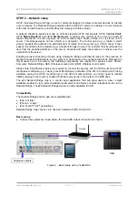
Figure 1 – Network Bridge front panel

