15
NOTE:
There are many available unit configurations for the Mini-Plus ceiling
units, therefore; be sure to identify the unit type and style before installing. For
instance there may be split condenser/condensing unit sections requiring
separate or shared power.
Note to Installing Contractor:
Condensation formation and frequent
humidifier flushing (when humidifier is installed) are normal functions of this
equipment. Drain connections must be made to ensure proper water removal.
Unit will require drain connections for condensate removal and water
connections possibly for humidifier (when installed) makeup water, condenser
water, chilled water and/or hot water. Installation of units above equipment that
could sustain water damage should be avoided.
Horizontal Airflow Units
All Mini-Plus ceiling units have horizontal airflow configuration with a 24
” (610 mm) tall evaporator
section. Duct collars are factory provided for the supply and return air duct flanges.
Installing/Mounting
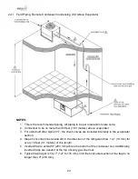
Four (4) threaded support rods must be securely attached to the building structure. Two field provided
support channels connect to the pairs of threaded support rod. See
for typical DAP installation method.
Raise the evaporator section with an appropriate lifting device. Attach washers, nuts and jam nuts to
each threaded rod. Tighten the nuts so the weight is supported evenly by the four rods and the unit is
level.
Vertical Airflow Units
The evaporator sections with optional vertical airflow (available on 2.5 and 3-Ton units only) are
28.5”
(724 mm)
high and are typically mounted over a standard 2’ (0.6 m) x 4’ (1.2 m) T-bar ceiling grid
supported by four (4) threaded rods.
The four (4) threaded support rods must be securely attached to the building structure. Raise the
evaporator section with an appropriate lifting device. Attach washers, nuts and nut jams to each
threaded rod. Tighten the nut so the weight is supported evenly by the four rods and the unit is level.
Be certain to allow for the depth of the supply/return air plenum when figuring the height of the unit in
the ceiling space.
The 5” (127 mm) tall vertical supply/return plenum assembly is attached to the bottom of the evaporator
section once the evaporator section is installed. Six (6) screws fasten the plenum to the evaporator
section. The supply/return air grilles should be temporarily removed for access during installation. The
plenum typically mounts flush to the ceiling grid (depending on available space above unit).
Summary of Contents for DA PA-04
Page 1: ......
Page 81: ...DAP IOM_10 2022 ...


