6
SARA manual / SARA - SUB
4.- Assembly of GS-PL-SARA. Angle settings.
Stability, max and min angle and max
number of units
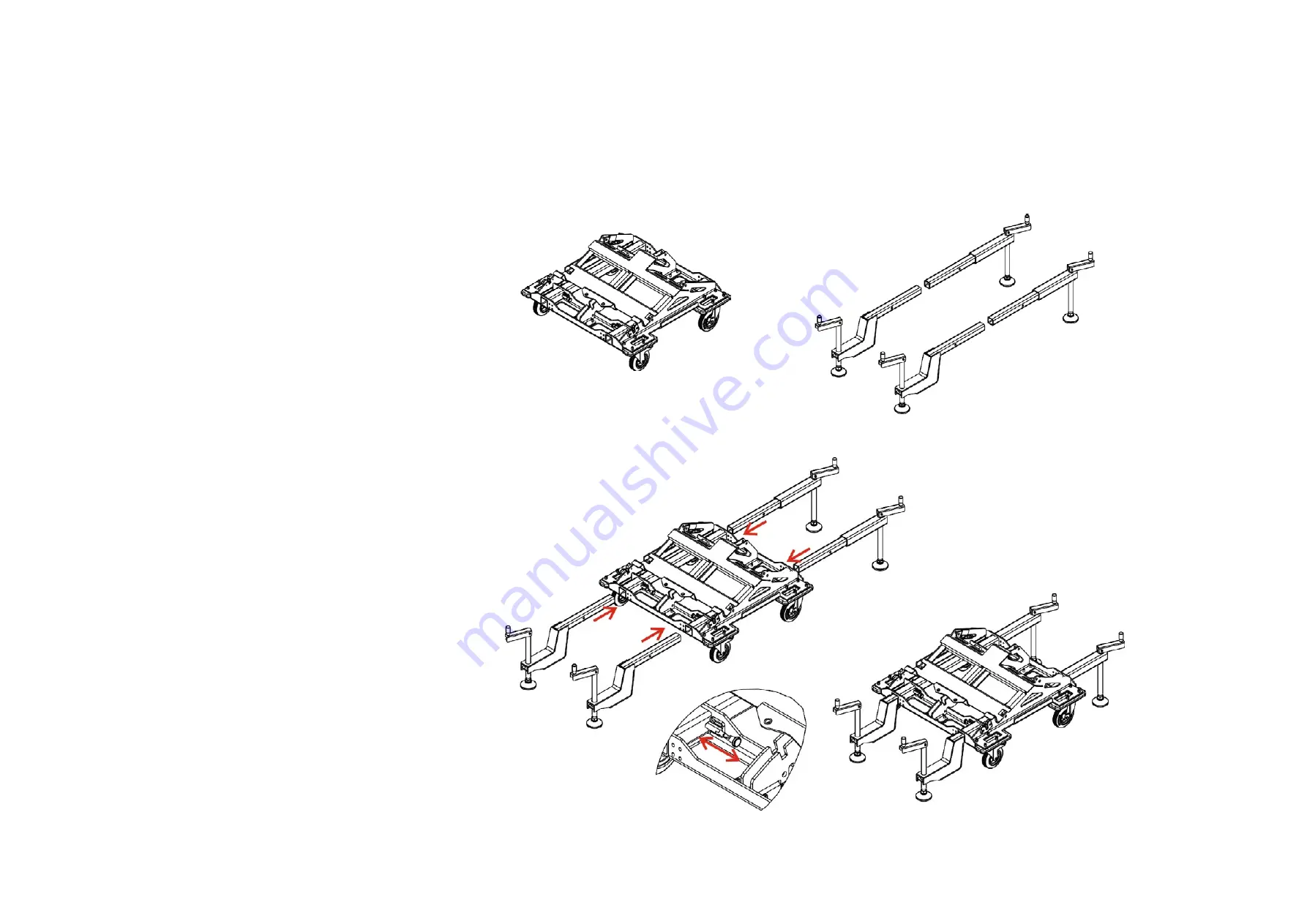
Fig.1
The figure shows the PL-SARA (WLL=160
kgf) accessory.
Fig.2
The GS-PL-SARA accessory can be at-
tached to the PL-SARA to provide addi
-
tional stability in ground stacked SARA
(WLL=160kgf) applications.
Fig.3
The figure shows how the different parts
of the accessory fit into the correspond
-
ing slots, releasing the security latches
included. Note that the elbow pieces are
mounted at the front of the platform,
while the remaining pieces go at the
back.
Fig.4
Note that the maximum number of units
that can be groundstacked remains 4.
PL-SARA platforms and the GS-PL-SARA
accessory are designed for maximum
stability with a ±14° tilt above the horizon
-
tal, regardless of the splay angle between
the 4 SARA units that can be stacked on
them.
When using the GS-PL-SARA, make sure
that the platform and accessories are
mounted on a firm surface.
Fig. 2
Fig. 1
Fig.3
Fig. 4


