background image

17

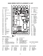
530B SERIES PARTS PLACEMENT & LIST

R4

R3

R5

R9

C2

+

+

C1

C7

C10

+

C12

+

C11

+

CR3

CR2

SW1

T1

D12

CR1

C3

C6

C4

C5

D11

D9

D10

D2

D1

R15

+

+

C13

C14

JU1

JU5

1

15V

1            2            3            4

5            6            7            8

JU3

CN1

JU6

R43

RESISTORS

CAPACITORS

MISCELLANEOUS

ACTIVE DEVICES

DIODES

R1
R2
R3
R4
R5
R6
R7
R8
R9
R10
R11
R12
R13
R14
R15
R16
R17
R18
R19
R20
R21
R22
R23
R24
R25
R26
R27
R28
R29
R30
R31
R32
R33
R34
R35
R36
R37
R38
R39
R40
R41
R42
R43

220K
5K TRIM (MIN)
47K
300K
10K
4.7K
250K TRIM (ACCEL)
1K
27K
4.7K
250K TRIM (DECEL)
1K
47K
4.7K
47

 1/2W

91K 1/2W
180K 1/2W
470

47K
6.8K
300K
1K
47K
470K
10K
680K
22K
2.2K
1K
220K
390

390

39K
1K TRIM (CUR)
2.2K
470

50K TRIM (MAX)
100

 TRIM (I.R.)

.SEE BELOW
100K
SEE BELOW
33K
100K

C1
C2
C3
C4
C5
C6
C7
C8
C9
C10
C11
C12
C13
C14

.01µF 63V
1µF 50V N.P.
.01µF 400V
.01µF 400V
.068µF 250VAC
.01µF 400V
.01µF 63V
NOT USED
.22µF 250V
150µF 16V
47µF 16V
470µF 50V
1µF 50V N.P.
.1µF 63V

D1
D2
D3
D4
D5
D6
D7
D8
D9
D10
D11
D12
D13
D14
D15
D16

S6A4
S6A4
1N4005
1N4005
1N914B
1N5233B
1N914B
1N5242B
1N4005
1N5233B
1N4005
1N4005
1N914B
1N4005
1N4005
1N4005

Q1
Q2

U1
U2
U3
U4

2N4124
LM78L12 REG.

LM358 IC
LM324 IC
3052 MOC
L512F BRIDGE

CN1
CR1
CR2
CR3
F1
F2
JU1
JU2

JU3
JU5

CT60R16USB CONNECTOR
T73 RELAY
SEE BELOW
SEE BELOW
20A FUSE
20A FUSE
SEE BELOW
WC16WH2.5SL JUMPER WIRE
  (SEE MANUAL “JUMPER WIRES”)
3 POS. MALE CONN. W/JUMPER
SEE BELOW

ALL RESISTORS 1/8W UNLESS SPECIFIED.

U1

R2

R7

R11

R37

R38

R34

F1

Q1

C9

P2-13

P2-12

P2-11

P2-10

P2-9

P2-8

P2-6

P2-5

P2-4

P2-3

P2-1

D3

MOV1

P1-1

P1-2

P1-3

P1-4

P1-5

P1-6

P1-7

R39

U4

P2-7

P2-2

JU2

R8

R12

R36

R27

R35

R25

R1

R24
R20
R19
R42

R32

R31

R33

R6

R13

R14

D4

D6

D5

R10

U2

R28

R21

D7

U3

R30

R22

D13

D15

Q2

F2

D14

MOV3

MOV2

R17

R16

D8

D16

R18

P3

MIN

ACCEL

DECEL

MAX

I.R. COMP

CUR LIM

GND        AC          AC       +ARM      -ARM    -FIELD   +FIELD

R41

R26

R40

R23

+3V

R29

530BC CHANGES:

CR2
CR3
JU1
JU5
R39
R41

NOT USED
NOT USED
RLB2503S RAIL
RLB2503S RAIL
.015

 5W

1K 1/2W

+7V

JU6
MOV1
MOV2
MOV3
PCB
P1
P2
P3
SW1
T1

WC16GN3.5 WIRE
275V G-MOV
275V G-MOV
275V G-MOV
A-4-2563C PRINTED CIRCUIT
7 POS. TERMINAL STRIP
13 POS. TERMINAL STRIP
1/4" MALE SPADE PIN
115/230VAC SWITCH (DPDT)
DST428 TRANSFORMER

530BRC CHANGES:

CR2
CR3
JU1
JU5
R39
R41

T9A RELAY
T9A RELAY
NOT USED
NOT USED
.015

 5W

NOT USED

530BRE CHANGES:

CR2
CR3
JU1
JU5
R39
R41

T9A RELAY
T9A RELAY
NOT USED
NOT USED
.015

 5W

NOT USED

533BC CHANGES:

CR2
CR3
JU1
JU5
R39
R41

NOT USED
NOT USED
RLB2503S RAIL
RLB2503S RAIL
.005

 5W

1K 1/2W

-6 OPTION CHANGES

C9
D13
R30

.033µF 400V
NOT USED
10K

-15A OPTION CHANGES

R13

180K

Summary of Contents for 530B Series

Page 1: ...B CONTROL SERIES P O Box 10 5000 W 106th Street Zionsville Indiana 46077 Phone 317 873 5211 Fax 317 873 1105 www dartcontrols com Instruction Manual Variable Speed DC Control LT530B 0505 CONTROLS A 5 3271B ...

Page 2: ...ered by other than DCI or to any article which DCI determines has been subjected to improper use DCI assumes no responsibility for the design characteristics of any unit or its operation in any circuit or assembly This warranty is in lieu of all other warranties express or implied all other liabilities or obligations on the part of DCI including consequential damages are hereby expressly excluded ...

Page 3: ...ng The trimpots would need readjustment see Trimpot Chart for approximate settings Q Can I use the 530B Series as a Current Follower A Yes there is a field installable 5 or 7 option shown in Options section Q Can I use the 530B Series on Tachometer feedback A Yes see Tach P2 9 under Terminal Strip Wiring P2 Q Can I use the Stop P2 11 Start P2 13 and Common P2 12 to stop start the control on the C ...

Page 4: ...kwise rotation of the I R COMP trimpot will increase gain compensation CUR LIM Current Limit Provides protection from excessive arm ature current by limiting the maximum armature current the control can provide This enables adjustment of the maximum torque the motorcandeliver SetCurrentLimit CUR LIM at125 oftherated motorcurrent Clockwiserotationofthe CUR LIM trimpotincreas es the torque current t...

Page 5: ...M DAMAGE TO THE CONTROL WIRING PROCEDURE 1 Size all wires which carry armature or line current to handle currents AS SPECIFIED BY NATIONAL STATE AND OR LOCAL CODES All other wires may be 20AWG or smaller as permitted by local code 2 Control wire Pot Tach etc should be separated from all the Armature Field if Shunt Wound and the AC wires when routed in conduits or in wire trays The enclosed version...

Page 6: ... 100 200V make sure the highest value is connected TERMINAL STRIP WIRING P2 The 530B Series uses a 13 position barrier type terminal strip for control connections CAUTION NONE OF THE P2 TERMINALS SHOULD BE EARTH GROUNDED P2 1 OVER CURRENT OUT Can be used to signal that the control is in current limit It can also signal other devices or alarms This is a low level logic signal which goes high when t...

Page 7: ...RPM OR 7 volt per 1000 RPM tachometer should be used P2 10 PILOT LIGHT Connecting point for on off neon indicator lamp The remaining lead will be connected to P2 11 P2 11 STOP Install one or more normally closed stop switches in series between STOP P2 11 and COMMON P2 12 Not active on C version P2 12 COMMON Mid point of Start Stop switches Not active on C version P2 13 START Install one or more no...

Page 8: ...Acceleration and Deceleration adjustments and should be set for your particular application requirements The TRIMPOT CHART isapproximateandisvalidwhenusingaspeedpotora0to12VDCinputsignaltocontrolthespeed Operationofthecontrol beyond 10 of normal line voltage is not recommended and could result in readjustments These settings are permanent periodic readjustment is normally not needed NOTE Use only ...

Page 9: ...ser 1 Clockwise trimpot rotation increases length of deceleration time needed for the control to reach zero speed 8 Adjustment procedure continued MIN ACCEL DECEL MAX I R CUR LIM HP VOLTS 1 8 115 1 6 115 1 4 115 1 3 115 1 2 115 3 4 115 1 0 115 1 4 230 1 3 230 1 2 230 3 4 230 1 0 230 1 5 230 2 0 230 NOTES These settings apply when using a 5000Ω speedpot This chart cannot be used with certain Option...

Page 10: ... IR COMP CUR LIM 13 12 11 10 9 8 7 6 2 1 P2 P1 EARTH GROUND VAC INPUT VAC INPUT DC MOTOR OPTIONAL FOR SHUNT WOUND MOTORS ONLY FUSES RELAY 1 2 3 4 5 6 7 AC N ARM ARM FIELD FIELD GND AC L 5 4 3 customer supplied wiring factory supplied wiring SPARE REV 2 JUMPER WIRE JU2 PILOT LAMP STOP COMMON TACH INPUT VOLTAGE SELECTOR SWITCH not active on C version Model 530BC and 533BC C Version 115V NOTE FOR HOO...

Page 11: ...age Model 530BRE RE Version 115V P3 PROVIDES SUPPORT AND TRIGGERING FOR OPTIONS OVER CUR OUT AMP REF POT LO POT WIPER POT HI REV 1 START red orange white SPEEDPOT MIN ACCEL DECEL MAX IR COMP CUR LIM 9 8 7 6 2 1 P2 P1 EARTH GROUND VAC INPUT VAC INPUT DC MOTOR OPTIONAL FOR SHUNT WOUND MOTORS ONLY FUSES RELAY RELAYS BLACK RED WHITE START STOP MOMENTARY ACTION SWITCH PILOT LAMP 1 2 3 4 5 6 7 AC N ARM ...

Page 12: ...EEDPOT WIPER LO HI SPST CONTROL MODIFICATIONS continued 4 Option See below for installation and availability Jog This option is factory installed on the RE version only S2 is located on the cover and disables the latch circuit of the power relay s allowing the power switch to jog the drive The C and RC versions use customer supplied switch and wiring in addition the C version uses a customer suppl...

Page 13: ...ntil you just reach your maximum speed setting For enclosed models use 7 option Input impedance 500 ohms or less This option replaces the speedpot with a 4 20 ma signal to control speed The current signal input can be either grounded or ungrounded The board sets on spacers screwed to terminals P1 3 P1 4 and P1 5 on the main board using long screws The current source connects to the and two positio...

Page 14: ...e or to deadband the point just before you begin to get an output 3 Input a 20 ma current signal to the control and set the Max trimpot to the desired maximum speed setting 4 Switch the control to the Manual mode setting and adjust the Balance trimpot CCW as needed to attain your required manual mode maximum output speed Adjustable form 50 to 100 of maximum Auto mode setting 5 Switch the control b...

Page 15: ...r field 5Ω30W optionboardmounted 36MA 115VAC factory only 5Ω50W extrusionmounted 38M 230VAC factory or field 10Ω30W optionboardmounted 38MA 230VAC factory only 10Ω50W extrusionmounted Warning The addition of this option no longer allows for dual voltage operation of the 530B series board The 115 230 VAC input selector switch 530B series board must be set for the proper VAC input rating of the 36M ...

Page 16: ...Diagrams Without Options IN CASE OF DIFFICULTY PROBLEM POSSIBLE CAUSE S CORRECTIVE ACTION S Motor doesn t operate Armature output voltage cannot be adjusted out put is a constant DC level Motor stalls or runs very slowly with speed control turned fully CW Motor hunts Repeated fuse blowing Motor runs but will not stop Replace fuse Install proper service Adjust speedpot CW to start Replace motor bru...

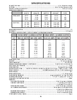
Page 17: ...Ω Ω Ω Ω Potentiometer OR 0 to 10 VDC isolated signal SPEED RANGE 50 1 SPEED REGULATION 1 of base speed TACHOMETER FEEDBACK jumper selectable 3V or 7V per 1000 RPM TEMPERATURE RANGE 10 to 45 C ambient 15 to 115 F TRANSIENT VOLTAGE PROTECTION G Mov TRIMPOTS ACCELERATION RANGE 0 3 to 12 seconds adjustable CURRENT LIMIT RANGE 1 to 20 Amps 1 8 to 2 H P CURRENT LIMIT RANGE 2 to 30 Amps 1 5 and 3 H P DEC...

Page 18: ...2 CR3 F1 F2 JU1 JU2 JU3 JU5 CT60R16USB CONNECTOR T73 RELAY SEE BELOW SEE BELOW 20A FUSE 20A FUSE SEE BELOW WC16WH2 5SL JUMPER WIRE SEE MANUAL JUMPER WIRES 3 POS MALE CONN W JUMPER SEE BELOW ALL RESISTORS 1 8W UNLESS SPECIFIED U1 R2 R7 R11 R37 R38 R34 F1 Q1 C9 P2 13 P2 12 P2 11 P2 10 P2 9 P2 8 P2 6 P2 5 P2 4 P2 3 P2 1 D3 MOV1 P1 1 P1 2 P1 3 P1 4 P1 5 P1 6 P1 7 R39 U4 P2 7 P2 2 JU2 R8 R12 R36 R27 R3...

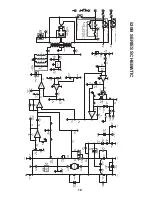
Page 19: ...100W FIELD P1 6 SW SW R30 220K R33 39K 12V R23 47K R1 220K R26 300K 12V 1 2 U3 3052 MOC 6 4 U3 3052 MOC 5 6 7 U2 2 R22 1K P3 TRIGGER 1 4 SPADE 3 2 1 U2 1 4 11 12V R20 6 8K R19 47K 12V R25 10K R24 470K C7 01µF 63V R21 300K 12V R18 470W NF D8 1N5242B AC2 SW D1 S6A4 D2 S6A4 AC1 SW MOV3 275V G MOV D9 1N4005 D10 1N5233B FIELD P1 7 FIELD 12V D7 1N914B CR3 CR2 CR1 F1 F2 AC2 AC1 P2 13 N O N C P2 12 P2 11 ...

Page 20: ...873 1105 Indiana productionandhead quarters facility with over 2 000 000variablespeedunits in the field In addition to the standard off the shelfproducts youcanse lect from a wide variety of op tions to customize controls for your specific application For further information and appli cationassistance contactyour local Dart sales representa tive stocking distributor or Dart Controls Inc Dart Contr...

Reviews: