Lay out the parts listed below. Refer to the ‘PARTS Stage 2’ section.
•
Homing Trigger
•
2x Belts
•
Belt Hub
•
4x Rail Bracket
•
2x Motor Bracket
•
2x Motors
•
2x Motor Pulleys
•
18x M3x30mm Screws
•
18x M3 Washers
In addition, lay out the parts listed below.
•
2x Long Rails
•
2x Short Rails
You will also need a
2.0mm Hex Tool, a 2.5mm Hex Tool and a 3.0mm Hex Tool.
STAGE 2 GANTRY ASSEMBLY
•
10x M3 Nuts
•
8x Shoulder Bolts
•
4x M5 Nuts
•
4x M5 Lock Nuts
•
4x M5 Washer
•
16x Flanged Bearings
•
4x Spacers
•
4x Gantry Carriage Housings
•
4x Linear Bearings
•
Laser Carriage
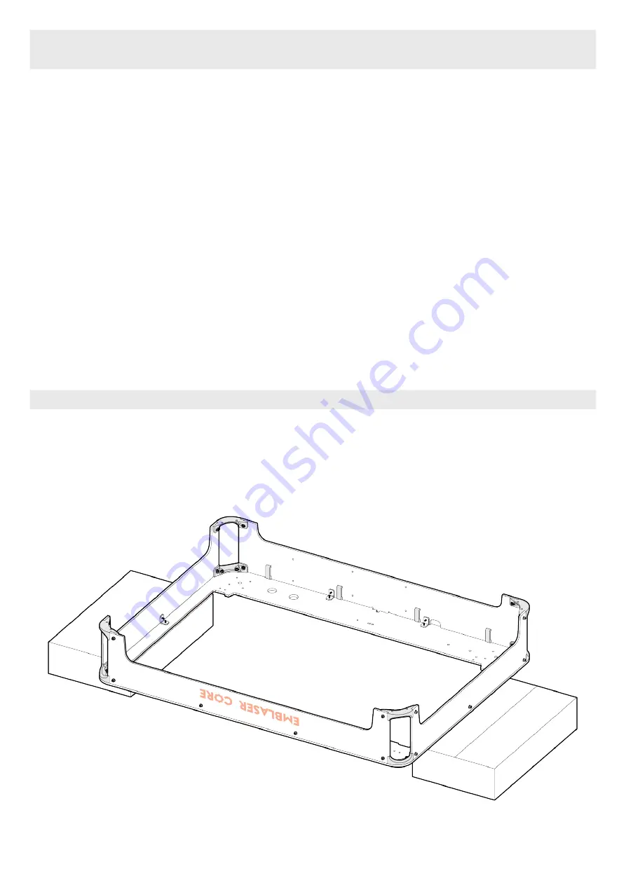
Step 2.01
16
Flip the
Frame Assembly over and rest it on a pair of the small boxes included in the packaging.
Summary of Contents for Emblaser Core
Page 1: ...Emblaser Core Assembly Manual Rev 1 32 User Assembly Manual English Darkly LabsR Kit Rev 1 0 ...
Page 13: ...Step 1 04 Place the 4x Cable Management Clips in the recesses on the Rear Panel 13 ...
Page 21: ...21 Step 2 06 Assemble the four Idle Pulleys ...
Page 33: ...33 33 Step 2 16 Route the Belt around the two Lower Position Idle Pulleys as shown ...
Page 35: ...35 35 Step 2 18 Route the Belt behind lower position pulley in the Gantry Carriage ...
Page 41: ...41 41 Step 2 22 Route the Belt around the two Upper Position Idle Pulleys as shown ...
Page 42: ...42 42 Step 2 23 Pass the Belt through the Gantry Carraige and around the Motor Pulley ...
Page 43: ...43 43 Step 2 24 Route the Belt behind lower position pulley in the Gantry Carriage ...
Page 52: ...Fold the Driver Board Cover as shown in the diagram Step 3 07 52 52 ...
Page 68: ...Attach the Rubber Feet to the Base Plate as shown below Step 8 03 68 68 ...
Page 76: ...Connect Workspace Camera cable to the Controller Board socket indicated Step 03 76 76 ...


