background image


PCIe-OPT01 Users Manual (Rev 1.0) 


                                                                  -

25-                                                     

http://www.daqsystem.com


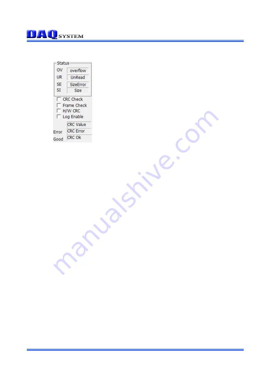
4.10    STATUS related functions 


It shows the number of the following 4 error states that occur during image transmission. 

“OV”

: Overflow 

“UR”

: UnRead 

“SE”

: SizeError 

“SI”

: Size 


“CRC Check”

: Activates the LVDS Check Sum function. 

“Frame Check”

: Activates frame CRC. 

“H/W CRC”

: Activates hardware CRC. 

“Log Enable”

: Activates the log screen. 


CRC Value

: Shows CRC value when checking CRC. 

CRC ERROR

: Shows the number of CRC errors when checking CRC 

CRC OK

: Shows the number of CRC OKs when checking CRC 


Summary of Contents for PCIe-OPT01

Page 1: ...Q system is believed to be accurate and reliable However no responsibility is assumed by DAQ system for its use nor for any infringements of patents or other rights of third parties which may result from its use No license is granted by implication or otherwise under any patent or copyrights of DAQ system The information in this document is subject to change without notice and no part of this docu...

Page 2: ...ctor 3 Installation 3 1 Hardware Installation 3 1 1 Product Contents 3 1 2 Installation 3 2 Drive Installation 4 Sample Program 4 1 Board Related Function 4 2 Image Frame Related Function 4 3 Clock Related Function 4 4 Power Digital IO Related Function 4 5 I2C Related Function 4 6 Auto Test Related Function 4 7 SPI Related Function 4 8 OS SPI Related Function 4 9 MISC Related Function 4 10 STATUS ...

Page 3: ...ided in the form of a source so that the API provided to use the board can be briefly tested so the user can modify and use it For more information on this please refer to Chapter 4 Sample Program The PCIe OPT01 board uses one SFP Small Form Factor Pluggable optical module The interlocked board is used with the MIPI OPT06 board that receives the C PHY or D PHY signal of the MIPI sensor or the MIPI...

Page 4: ...trolled by the program API MIPI SENSOR C PHY or D PHY MIPI OPT06 PCIe OPT01 Figure 1 1 PCIe OPT01 MIPI OPT06 Example Using Figure 1 2 shows the connection between PCIe OPT01 and MIPI OPT08 board that receives D PHY signal or parallel signal of MIPI sensor It is a board that transmits signals received through optical transmission to a PC through the PCI Express 4x interface method The operation of ...

Page 5: ... A C E G J L N R J5 Y1 J11 J1 J2 J3 Figure 2 1 PCIe OPT01 Layout 1 SFP CN1 SFP Small Form Factor Pluggable Cage 2 FPGA U3 All functions of the board are controlled through this FPGA Logic 3 DDR Memory REF1 REF2 Save the image frame 4 Regulator U1 U2 U5 U6 Supply the power used by the board 5 There are several LEDs on the board and each description is as follows J1 CN1 Red Rx signal Green Tx Signal...

Page 6: ... copper networking cable The SFP is connected by a module that connects to the cage and connector and there are Tx Transceiver and Rx Receiver together Figure 2 2 SFP SFP Cage Table 1 CN1 SFP Connector Description No Name Descriptuon Remark 1 VeeT Transmitter Ground 2 TxFault Transmitter Fault 3 TxDisable Transmitter Disable 4 SDA Serial Interface Data Line 5 SCL Serial Interface Clock 6 MOD ABS M...

Page 7: ...gh Bandwidth 10 VeeR Receiver Ground 11 VeeR Receiver Ground 12 RD Receiver Data 13 RD Receiver Inverted Data 14 VeeR Receiver Ground 15 VccR Receiver Power 3 3V 16 VccT Transmitter Power 3 3V 17 VeeT Transmitter Ground 18 TD Transmitter Data 19 TD Transmitter Inverted Data 20 VeeT Transmitter Ground Note For detailed specifications refer to the SFP standard document ...

Page 8: ...s designed to use up to 4 PCIe OPT01 boards simultaneously in one system PC Classification of each board can be set through the 4 pin DIP switch J4 in the board 1 ON OFF J4 2 Figure 2 5 J4 Switch Table 2 J4 Description 1 2 Description OFF OFF Board Number 0 ON OFF Board Number 1 OFF ON Board Number 2 ON ON Board Number 3 2 3 3 J8 Connector 12V FAN power connector 2 3 4 J10 Connector 12V power supp...

Page 9: ... etc 3 1 2 Installation Process Turn off the computer Remove the computer cover according to the computer manual Insert the product into an empty PCI Express slot If possible insert the boards in the order closest to the CPU Remove the blocked part from the back of the computer case in the slot where the board is inserted and then tighten the screws on the connection part between the bo ard bracke...

Page 10: ...n Windows 2000 SP4 or higher and Windows XP SP1 or higher First power off the PC plug the PCIe OPT01 board into the PCI Express Slot and turn on the PC When the Start New Hardware Search Wizard window opens as shown below select it as shown below and click the Next button 1 Select as below and click the Next button ...

Page 11: ...01 Users Manual Rev 1 0 11 http www daqsystem com 2 Select Driver from the enclosed CD and click the Next button 3 Click the Next button It indicates that the installation process is in progress as shown below ...

Page 12: ...em com 4 Click the Next button 5 When the installation is complete check whether the driver is installed normally in the following way 6 In My Computer Properties Hardware Device Manager check whether the multifunctional adapter PCIe OPT01 is installed ...

Page 13: ... 7 If it appears as shown in the figure below the installation was successful The picture above shows the screen where the PCIe OPT01 board is normally installed in the PC Note After initial installation it is recommended to reboot the PC for normal operation ...

Page 14: ...e screen as a video for easy user to understand In order to test the sample program the driver of the board must be installed first The sample program is provided in the form of a source so that the API provided to use the board can be briefly tested so the user can modify and use it Figure 4 1 Sample program FrmTest exe execution screen To use the sample program above API Application Programming ...

Page 15: ... After Dev After Init Get Res Checking the resolution After selecting the resolution to view on the screen click Set detected Check Auto View to see the video in real time 4 1 Board related functions 1 Device Open button Start the device of the selected board If it is 0 there is no device or connection is not established 2 Board If the board is multi assign the board number Currently you can selec...

Page 16: ...nly once when the power is first applied Select Video Data Mode from 8bit 16bit 24bit and 32bit 2 S Read button The sensor initialization file is read Depending on the address_data size 16_8 16_16 above it is possible to send commands to the INI file at a time or to use I2C read write commands line by line The structure and description of the ini file are as follows In the following example the ad...

Page 17: ...330B 0x04 0x330C 0x08 0x330D 0x05 0x330E 0x03 0x3318 0x65 0x3348 0xE0 0x0100 0x01 Streaming 3 Iint button Initialize the sensor by selecting SNI T1 T2 SPI 4 Go button Open the device and initialize it open the corresponding ini file and get the resolution All actions are executed at once 5 Check button Check the USB connection In case of error LVDS Check Error is displayed 6 Flush button Initializ...

Page 18: ...ser settings or image input format type No Skip There is no byte skip 5 th Skip When selected the 5th byte is skipped For example when the input data is Bayer with 10 bits the remaining 1 bit excluding RGB 3 bytes and 1 byte by 8 bits is stored in the 5th byte When Bayer is processed and displayed on the screen the 5th byte is not needed so it is used when removing it 3 th Skip When selected the 3...

Page 19: ... Clock In the above case it is set to 10MHz 3 Set 6M button Set the sensor clock to 6MHz 4 Set 16M button Set the sensor clock to 16MHz 5 A CHG toggle If checked Min Max It is possible to test by periodically setting the interval of the frequency specified as by Step Ex In the above case the frequency increases in 0 5MHz increments between 5 and 30MZ and the period increases in increments of 0 5 x...

Page 20: ...o board manual PCI_SDIO_XXXX Sensor GPIO General Purpose I O MIPI OPT06 08 Refer to board manual PCI_DIO33_XXXX User 3 3V GPIO General Purpose I O MIPI OPT06 08 Refer to board manual PCI_PWR_DIO_XXXX Power GPIO GPIO General Purpose I O MIPI OPT06 08 Refer to board manual 3 Set Dir button Set whether to use each GPIO port as an input or output If the end bit is 0 it is an input and if it is 1 it is...

Page 21: ...and OS modes below 4 Reset Button Initializes the resources of the I2C system 5 Slave ID Slave ID Address Slave Register Address Len Address Value Size Data Len Data Value Size Addr Buf toggle When selected it is used in SYS mode and an address buffer is used instead of an address Data Data you want to transfer The above values are variables used for I2C Read or I2C Write 6 P B On or P B Off butto...

Page 22: ...lated functions 1 RUN toggle Test the board as a whole Test Period You can set the test period in seconds Stop on Err Stop error output Run2 Initializes the sensor and performs an image test DDR2 Reset Initializes the DDR memory Board Reset Initializes the board 2 Clear Error Log Button Clear the error log ...

Page 23: ... Buffer size Set DMA Size Button Set the DMA buffer size PCI ddr Reset Button Initializes the DDR memory 4 8 OS SPI related functions OS SPI Send Button Sends data to the sensor Send Bytes Size of bytes to be sent to the sensor Data0 0 data to be transmitted to the sensor Data1 Data to be transmitted to the sensor 1 ...

Page 24: ...sor I2C Off Turns Sensor I2C operation On Off Sensor Reset Set the sensor reset output to High or Low Sensor Enable Set the sensor s enable output to High or Low MCLK Off Turns the master clock output On Off Data Check If the frame data is an error it is counted in the box below View Skip Stop the video Log Enable Enables the log file at the top right View Once Shows the video once 1 Clr Button In...

Page 25: ...age transmission OV Overflow UR UnRead SE SizeError SI Size CRC Check Activates the LVDS Check Sum function Frame Check Activates frame CRC H W CRC Activates hardware CRC Log Enable Activates the log screen CRC Value Shows CRC value when checking CRC CRC ERROR Shows the number of CRC errors when checking CRC CRC OK Shows the number of CRC OKs when checking CRC ...

Page 26: ...ce Support a Full Camera Link Interface One SFP Small Form Factor Pluggable Connectors with full support Link Speed 8Gbytes sec 256Mbyte Image Buffer H W and SDK is controlled by a programmable FPGA Image frame data transfer to PC Software Supported OS Windows XP 7 8 10 API Interface with Application through client DLL Sample Software Test Sample software for evaluation ...

Page 27: ...PCIe OPT01 Users Manual Rev 1 0 27 http www daqsystem com A 2 Board Size The external dimensions of the board are as follows 132 x 68 mm 132 55 68 ...

Page 28: ... www daqsystem com References 1 PCI Local Bus Specification Revision2 1 PCI Special Interest Group 2 How to install PCI DAQ Board DAQ system 3 AN201 How to build application using API DAQ system 4 AN312 PCIe OPT01 API Programming DAQ system ...

Reviews: