PCIe-FRM13 User’s Manual
24
3-4-2 Photo Coupler Output
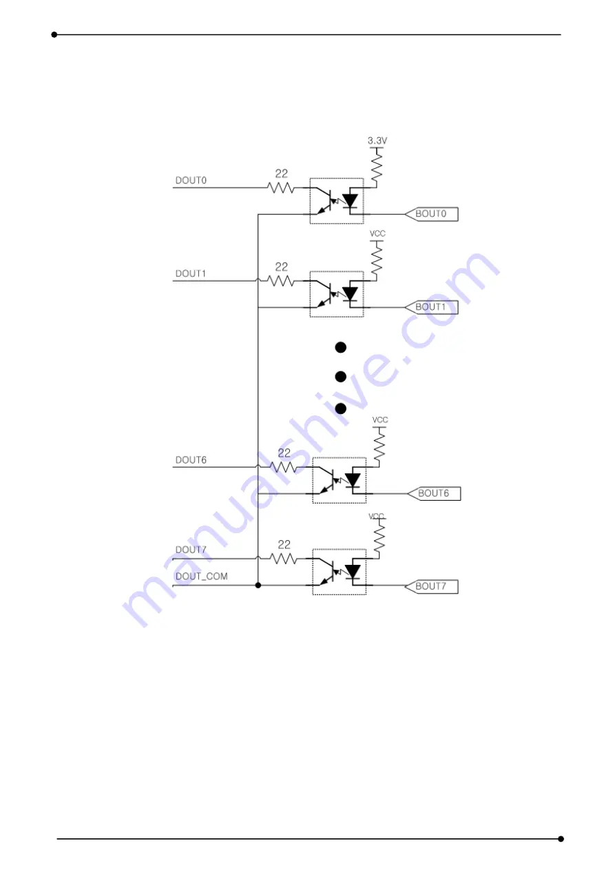
In the program, bits 7 to 0 of the output are connected as in [Figure 3-10].
[Figure 3-10. Photo-coupler Digital Output Circuit]
The photo-coupler output can be connected with other DIO boards of the DQ system or
connected with a cable (20 pins) through the J2 connector connected to the DSUB 15 pin
connector of the PCIe-FRM13 board, and in this case, output bits 7 to 0 are connected.


