7
Set Up and Operation
Before plugging the unit in, always make sure that the power supply matches the product specification
voltage. Do not attempt to operate a 120V specification product on 230V power, or vice versa.
Linking Satellites / Subwoofers
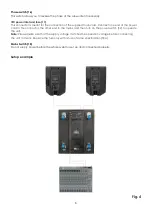
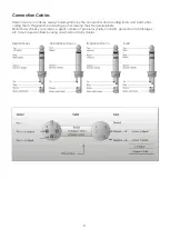
Connect the cables coming from the mixer to the balanced INPUT sockets of the K-18BA. Depending on
the mixer’s output sockets use either a jack or XLR cable. Link the units as shown in figure 4 on page 8.
Connect a standard XLR microphone cable from the first unit's THRU output socket to the second unit's
INPUT socket. Repeat this process to link subsequent units. Repeat this for each stack. Make sure that
when using multiple tops, they are placed with a proper projection angle.
Do not supply power before
all components of the system are
set up and connected properly.
Make sure
that the K- 18BA is always the last component, which is switched on! When shutting down, the K-18BA
should be the first component, which is switched off.
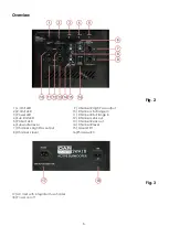
Below you will find a short description of the features from the K- 18BA :
Input limit LEDs (1 + 2)
The LED shows the status of the L-R limiters. If the LED lights green it means there is an input signal, if the
LED lights yellow, the limiting circuit is in soft limiting mode. If the LED lights RED, the limiter is in full limit
mode. We suggest you to set the input level with the L-R level controls in such way that the LED blinks
yellow occasionally. If the LED light up red continuously we strongly suggest you to lower the L-R Level
controls.
Power LED (3)
Indicates that the K-18BA is switched on.
Sub Limit LED (4)
The LED shows the status of the Sub limiter. If the LED lights green it means there is an input signal, if the
LED lights yellow, the limiting circuit is in soft limiting mode. If the LED lights RED, the limiter is in full limit
mode. We suggest you to set the input level with the Sub level control in such way that the LED blinks
yellow occasionally. If the LED light up red continuously we strongly suggest you to lower the Sub Level
controls.
Protect LED (5)
Indicates that the amplifier is in protection mode. This either caused by a short circuit in the output
load or a mismatch of impedance. Also check if the fans are not obstructed.
Subwoofer level (6)
This allows you to adjust the audio level for the subwoofer.
High Pass balanced out (7 + 9)
Use this socket to connect your active satellites.
Channel level (8+14)
This allows you to adjust the audio level for the satellites.
Full Range Input (10+11)
The input equipped with 3 pole XLR/ jack combo socket is electronically balanced to accept the (line)
signal from any mixing console.
Thru (12+13)
This parallel output allows you to connect more bass-cabinets together.
Ground Lift (15)
When this button is pressed, it separates the signal ground from the chassis ground, enabling you to
eliminate potential ground loops or low-frequency hum.
Summary of Contents for K-18BA
Page 1: ...K 18BA ORDERCODE D3375...
Page 14: ...2009 DapAudio...

