background image


IMIX 7.3 

Ordercode: D2351  

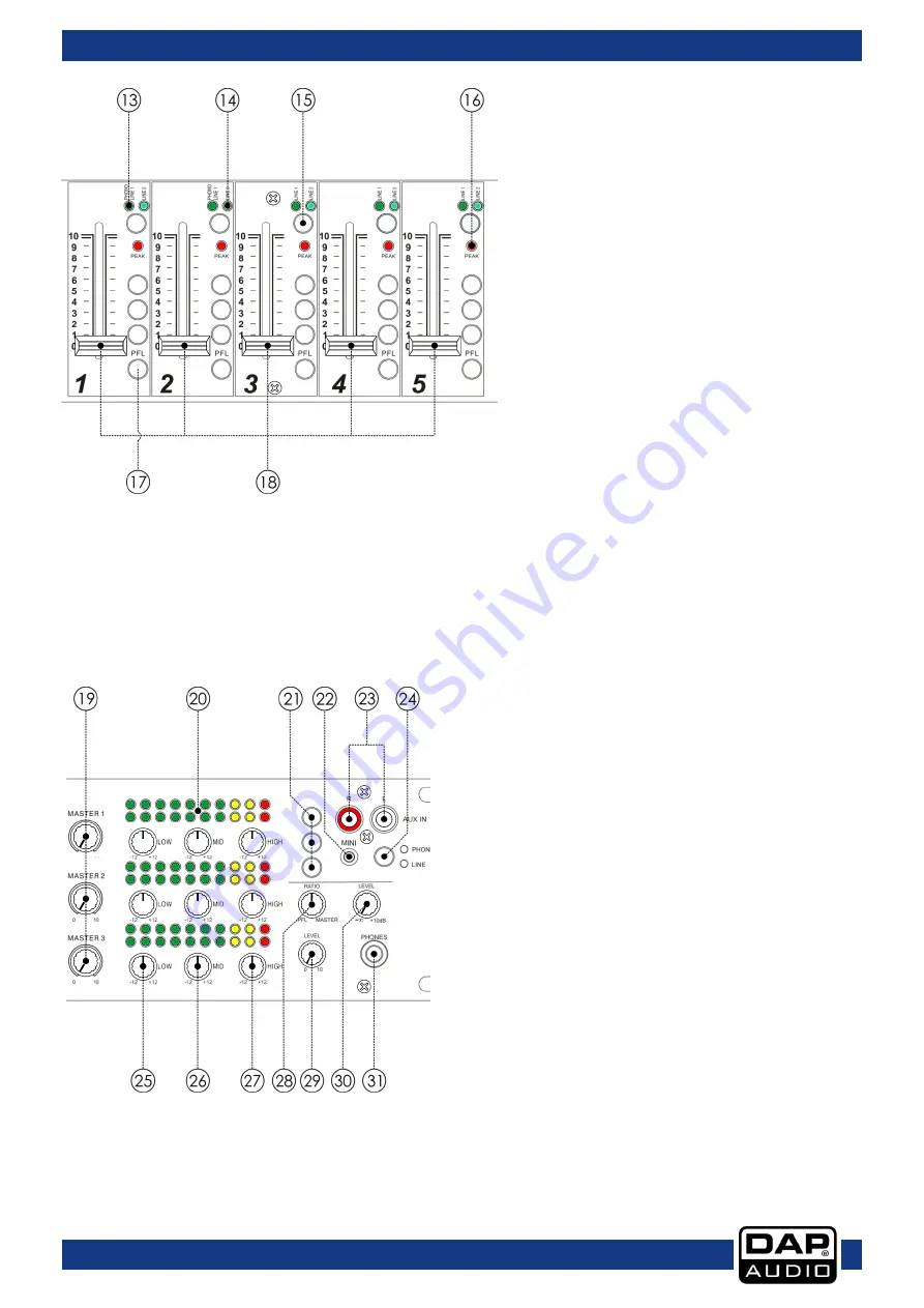
13.  Phono-line 1 LED 

Indicates that the phono-line 1 input is 

selected. 


14.  Line 2 LED 

Indicates that the line 2 input is selected. 
 

15.  Selection button (phono-line 1/line 2) 

With this switch you can choose between two 

sets of inputs per channel. 


16.  Peak LED 

The peak LED shows signal peaks in a 
channel’s incoming signal. If the red peak LED 
frequently blinks or constantly lights, the 
corresponding channel is likely to enter 
clipping and you have to reduce the input’s 
amplification using the corresponding gain 
(38-42) control on the back. The peak LED 
lights at a level of 8 dB below clipping. Make 
sure that the peak LED lights only briefly during 
dynamic peaks. 


17.  PFL button 

The PFL button (pre fade listening) is designed to route the channel input to the monitor section 
independent of the individual channel’s volume fader setting. It is possible to assign more than one 
channel simultaneous to the PFL bus. 


18.  Channel fader 

A logarithmic 50mm fader, which controls the volume of the corresponding channel. The overall volume 
is set with the master control.  


19.  Master control (master 1-3) 

You can adjust the output signal to the 

master 1-3 

outputs (48-52).


20.  Output signal VU-meter (master 1-3) 

This meter is a multi-step LED. The accurate level 
indication allows you to monitor the output signal 
level at anytime, and match with other devices. 
 

21.  Zone select buttons 

Use these 3 buttons to assign the channel to 1 or more 
master outputs. 
 

22.  Aux mini jack in connector 

Unbalanced stereo mini jack aux input for connecting 
a line/phones level device. Use the Phone/Line () 
switch to set up this input for connecting either 
headphone or line level output devices. 
 

23.  Aux RCA in connectors 

Unbalanced stereo RCA aux input for connecting a 
line/phones level device. Use the 

phone/line (24)


button to set up this input for connecting either 
headphone or line level output devices. 


Summary of Contents for IMIX-7.3

Page 1: ...IMIX 7 3 Highlite International B V Vestastraat 2 6468 EX Kerkrade the Netherlands Ordercode D2351 MANUAL ENGLISH...

Page 2: ...2 Operating Determinations 4 Connection with the mains 4 Return Procedure 4 Claims 4 Description of the device 5 Features 5 Overview 5 Front 5 Rear 6 Installation 6 Functions 7 Set Up and Operation 1...

Page 3: ...lation operation and maintenance of this system has to be qualified follow the instructions of this manual Before you initial start up please make sure that there is no damage caused by transportation...

Page 4: ...e DI boxes to balance unbalanced signals All incoming signals should be clear Make sure that the available voltage is not higher than stated on the rear panel Make sure that the power cord is never cr...

Page 5: ...sure to properly pack fixture any shipping damage resulting from inadequate packaging is the customer s responsibility Highlite reserves the right to use its own discretion to repair or replace produ...

Page 6: ...PFL button channel 1 5 Zone select button all channels Channel fader channel 1 5 Peak LED mic 1 2 Master control master 1 3 Low control mic 1 2 VU meter master 1 3 Mid control mic1 2 Zone select butto...

Page 7: ...nbalanced out connector Channel 3 gain control Channel 5 line 1 line 2 input connectors Channel 2 gain control Channel 4 line 1 line 2 input connectors Channel 1 gain control Channel 3 line 1 line 2 i...

Page 8: ...channel s equalizer section allows shaping of the incoming audio signal All mono input channels are fitted with 3 band EQ The high 6 and low 4 shelving controls have their frequencies fixed at 12KHz a...

Page 9: ...e fader setting It is possible to assign more than one channel simultaneous to the PFL bus 18 Channel fader A logarithmic 50mm fader which controls the volume of the corresponding channel The overall...

Page 10: ...ht amplifies the frequency range turning to the left attenuates the signal Minor changes to the Equalizer control usually produce the best results Try to avoid excessive enhancement of the mid band 28...

Page 11: ...put levels 39 Channel 4 gain control Channel 4 input level is determined by the gain control With the gain control you can adjust the line input sensitivity while optimally matching the incoming signa...

Page 12: ...e these outputs to connect an amplifier with unbalanced inputs 52 Master 1 XLR balanced out connectors Use these outputs to connect an amplifier with balanced inputs 53 Master 1 RCA unbalanced out con...

Page 13: ...discharges etc are caused entirely by using unsuitable or faulty cables Unbalanced Balanced For these applications the unit provides 1 4 TRS and XLR connectors to easily interface with most profession...

Page 14: ...again 4 If nothing happens after 30 seconds unplug the device 5 Return the device to your DAP Audio dealer Product Specification Input channels 2 x Microphone combo XLR Jack 11 x Line RCA 2 x Phono R...

Page 15: ...14 IMIX 7 3 Ordercode D2351 Block diagram...

Page 16: ...2013 DAP Audio...

Reviews: