background image

18

www.danvex.fi

6.

PREVENTION AND TROUBLESHOOTING

6.1 

    Frequency of inspection and maintenance

To prevent failure of units and assemblies of the dryer, it is necessary to periodically inspect

:


Knot

3-6 

months

12 

months

Filters

Filter cleaning. 

If the filter soiled replace it.

Fan

Dust and debris in the cooling groove 

on the surface of the motor housing 

must be removed. 

Check  terminals of engine wiring to make 

sure the wiring is not loose.

Check fan bearing lubrication 

and add lubricating oil. 

Check fan impeller for damage. 

If there are signs of corrosion, 

take immediate action.

Electric motor rotor

Check the drive belt for damage 

and correct operation

Check motor wiring 

and make sure wiring is not loose.

Check for signs of damage 

and overheating.

Heater

Remove debris and dust from 

the surface of the heater

Rotor

Check for signs of overheating and blockage. 

Clean the dust from the surface of the rotor.

Seals

Check for signs of damage and displacement.

If there is wear or damage, then a replacement is required.

Sensors 

of temperature 

and humidity

Check the performance of all external 

temperature and humidity sensors 

and, if necessary, calibrate them

.

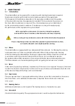
There is high voltage inside the block. Before any maintenance work, 

check that the device is powered off.

There is a high temperature zone inside the unit (heating section of the regenerator) 

that needs to be cooled down before maintenance.

Adjustment, maintenance and repair of the device must be carried out by qualified personnel. 

Relevant personnel should be aware of the high temperature and high pressure inside the unit.

Summary of Contents for AD-200

Page 1: ...Manual Desiccant dehumidifiers AD 200 AD 400 AD 550 rev 2 01...

Page 2: ...1 Enclosure 7 2 3 2 Conveying air circuit 7 2 3 3 Regeneration air circuit 7 2 3 4 Rotor 7 2 3 5 Rotor drive 7 2 3 6 Safety devices 7 3 INSTALLATION 8 3 1 Introduction 8 3 2 Transport and storage 8 3...

Page 3: ...thm of operation of the dryer components 16 5 MAINTENANCE 17 5 1 Introduction 17 5 2 Filters 17 5 3 Rotor 17 5 4 Gear motor 17 5 5 Heating device 17 5 6 Drive belt 17 6 TROUBLESHOOTING 18 6 1 Inspecti...

Page 4: ...ion and operation instructions Content General information about the management of the dehumidification process the principle of operation and maintenance standards system errors diagnostics and troub...

Page 5: ...he operator s responsibility for compliance with personal safety requirements at work and local safety standards During the installation and operation of equipment each employee must follow the instru...

Page 6: ...ith relative humidity below 35 and low dew point process air preparation systems single pass airflow systems manufacturing packaging storage testing and research of pharmaceutical products production...

Page 7: ...air passes through the filter into the rotor the moisture from the air is absorbed by the dehumidifying working sector of the rotor and the dehumidified air is expelled from the other side of the roto...

Page 8: ...at resistant composite material The composite material is a corrugated structure filled with a highly effective desiccant forming many small air flow channels contacting the air with a large area and...

Page 9: ...tdoor use To ensure proper maintenance for opening the service panels it is recommended that when installing the dryer leave a free space on all sides of about 800 mm The minimum width of the service...

Page 10: ...e ground or equipped with an additional inlet filter to prevent dust and debris from being sucked in The inlet must be away from possible sources of pollution such as exhaust gases steam and harmful g...

Page 11: ...t is particularly long or must be installed vertically it must be thermally insulated and a drain point provided at its lowest position The air duct outlet must be equipped with a metal grill or mesh...

Page 12: ...st be located outside the circuit to be dried Dry air must be evenly distributed in the room to be dried no duct connection to the process air inlet is required Installation diagram inside the dehumid...

Page 13: ...cal equipment must be carried out in accordance with the standards of the country in which the equipment is used and only by qualified experts It is forbidden to connect the dehumidifier to the mains...

Page 14: ...as temperature changes may affect the measurement process The scheme for connecting an external temperature and humidity sensor to the controller is shown in the general wiring diagram of the install...

Page 15: ...on of the remote sensor the lower panel displays the humidity set by the operator Hour meter displays the total running time for AD 200 and AD 550 models Ammeter displays the current in the recovery a...

Page 16: ...ork until the humidity is reaches 45 then turns off When the relative humidity level in the drying zone reaches 50 the dehumidifier will restart 3rd press buttons Setting Set 20 20 Humidity Sensor Cal...

Page 17: ...f the components is repeated manual shutdown of the dehumidifier by selecting the OFF mode middle position on the 3 position switch switching off the regeneration air heater and the working air fan th...

Page 18: ...with two independent filter elements for filtering the working and regeneration air Filters are installed at the inlet of the air duct and provide cleaning of the air entering the dehumidifier Cleani...

Page 19: ...iring is not loose Check for signs of damage and overheating Heater Remove debris and dust from the surface of the heater Rotor Check for signs of overheating and blockage Clean the dust from the surf...

Page 20: ...fuse the fan is damaged rotor damaged the electric heater is damaged check the fan and its motor check the rotor drive motor and belt check the electric heater The device does not starts no power sup...

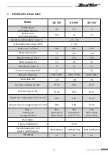
Page 21: ...nt A 6 10 22 Power consumption kW 1 3 2 4 5 Voltage frequency 230V 50Hz 230V 50Hz 230V 50Hz Noise level dB 45 60 65 Duct size working air mm D100 D125 D125 Duct size dry air mm D100 D125 D125 Supply d...

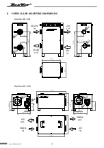
Page 22: ...EN IN REGEN IN AIR IN AIR IN REGEN OUT REGEN OUT 8 OVERALL AND MOUNTING DIMENSIONS DanVex AD 200 678 395 80 210 80 300 155 125 8 0 125 235 210 110 310 604 424 652 140 175 140 480 1 0 0 1 0 0 157 140 2...

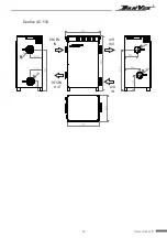
Page 23: ...22 www danvex fi 870 571 245 240 205 650 100 100 1 2 5 1 2 5 145 650 190 200 420 505 DanVex AD 550 AIR OUT AIR IN REGEN IN REGEN OUT...

Page 24: ...ECTION DIAGRAM DanVex AD 200 Process motor Gear motor Humidistat Plug Humidity sensor Rocker Switch Heater Regen motor 230V 16A RVV3 x 1 5 mm 2 x 3m AC230V 50Hz Control Panel FY 2010 JS M3 M1 M2 MAN A...

Page 25: ...minals for Humidity limit signal Humidistat Plug Humidity sensor Rocker Switch Communication terminals Heater Regen motor DanVex AD 400 230V 16A RVV3 x 1 5 mm 2 x 3m AC230V 50Hz Control Panel RVV2 x 0...

Page 26: ...er Reserved terminals for Humidity limit signal Humidistat Plug Heater Rocker Switch Communication terminals Humidity sensor DanVex AD 550 AC230V 50Hz 3 x 4 mm 2 x 3m Control Panel RVV2 x 0 5 mm 2 x 1...

Reviews: