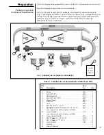
STEP 5:
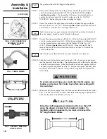
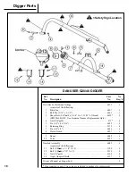
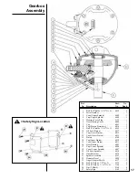
Stand the digger gearbox in an upright position resting on the spindle. Lower the
boom to the gearbox, and attach the gearbox to the boom using pin (PN 6056)
and retaining rings (PN 2172). Avoid pinch points as the gearbox pivots.
STEP 6:
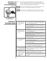
Raise the boom to the highest point, and make sure there is no contact between
the boom and the tractor and any point. If necessary, adjust the travel of the
boom to provide maximum travel without boom-tractor contact. Refer to your
tractor operating manual for instructions on three-point hitch adjustments or
refer to
Installation Troubleshooting.
Assembly &
Installation
(continued)
9
Personal protection
equipment including hard
hat, safety glasses, safety
shoes, and gloves are
recommended during
assembly, installation,
operation, adjustment,
maintenance, repair,
removal, or movement of
the digger. Do not allow
long hair, loose fitting
clothing, or jewelry to be
around moving parts.
W A R N I N G
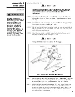
Instructions (Refer to Fig. 2.)
STEP 1:
Attach the yoke (PN 6051) to the boom (PN 6045) using pin (PN 6055) and
retaining rings (PN 2172). Stabilize components to avoid pinch points during
assembly.
STEP 2:
Attach the boom to the tractor upper link bracket with the tractor upper link pin.
Avoid pinch points around the pin during assembly.
STEP 3:
Slip the lower link ball joints over the digger yoke link pins, and secure with the
klik pins provided with your tractor hitch. Keep hands away from pinch points
while sliding components together.
STEP 4:
Adjust the sway stabilizers as tightly as practical for best performance and to
keep the post hole digger from swaying side-to-side.
Sway stabilizers must be used with the digger.
C A U T I O N
Because of the weight of some components, and because
some components are difficult to balance, two people are
required for safe assembly and installation of this
equipment.
C A U T I O N
FIG. 3 - THREE-POINT HITCH REPRESENTATION


