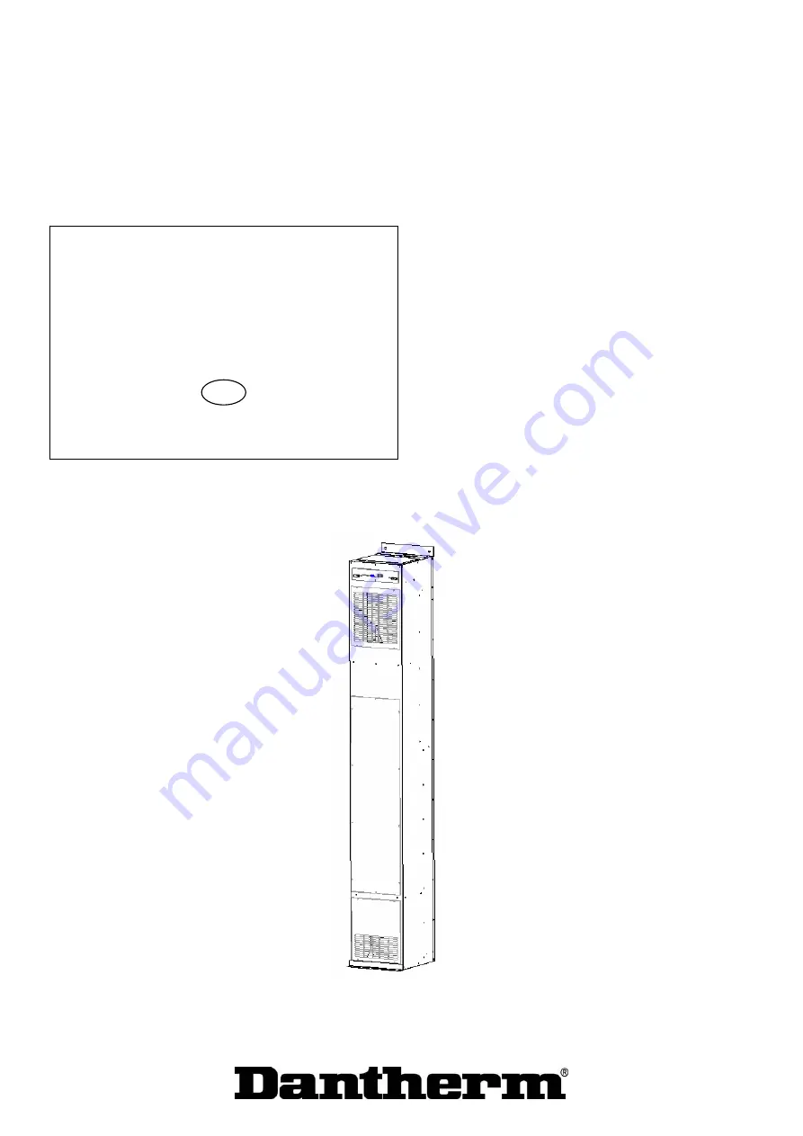
RBS 800
EN
N0. 910002 • rev. 2.0 • 01.12.2004
Page 1: ...RBS 800 EN N0 910002 rev 2 0 01 12 2004...
Page 2: ...hold for trykfejl og ndringer Dantherm can accept no responsibility for possible errors and changes Irrt mer und nderungen vorbehalten Dantherm n assume aucune responsabilit pour erreurs et modificati...
Page 3: ...tions Serial number This manual covers units produced after the below date which is to be found in the first 6 digits in the serial number on the unit type plate yy mm dd 041201 Contents This service...
Page 4: ...able of contents 4 General information 6 Product and functional description 7 General description 8 Fan 9 Damper 10 Heating 11 Set points 12 Test facility 13 Comfort temperature during visit by techni...
Page 5: ...eplace the damper motor 35 How to replace the temperature sensors 37 Fault finding guide 38 Hotline 40 Recycling of the unit 41 Service agreement 42 Technical information 43 Technical data 44 Dimensio...
Page 6: ...anual or part of it is not allowed without written permission from Dantherm A S Reservations Dantherm A S reserves the right to make changes and improvements of the product and the service manual at a...
Page 7: ...800 Contents The section contains the following topics Topic See page General description next page Fan 9 Damper 10 Heating 11 Set points 12 Test facility 13 Comfort temperature during visit by techni...
Page 8: ...by the control panel are Heating element Damper motor Fan Terms The following terms are used in this manual Outdoor air temperature the temperature of the air outside the room or container This is the...
Page 9: ...ctive of the temperature The fan is monitored with the assistance of a pulse generator fitted in the fan Back up function RBS 800 can also be used as back up unit for other cooling units that are resp...
Page 10: ...amper mode is conditioned by the fact that the set point on the control panel has been reached This set point relates to the return air temperature and can be set from 25 C to 35 C Learn more about th...
Page 11: ...error relays See the section entitled Fault finding guide page 38 for additional details However a simultaneous AC power failure will result in this error being rejected In the event of a fan error th...
Page 12: ...e made on the front of the control panel and it can be set from 25 C to 35 C Telemetry or DanView When Telemetry or DanView display is used the set point areas extends to Heat 10 C to 20 C Damper 20 C...
Page 13: ...fail if and when detected If any fail is detected during the test the LED will flash with a frequency of 1 Hz for 30 seconds after the test is done to indicate some fault were detected The table below...
Page 14: ...there is a button marked Occupied see drawing above Press this button and hold it down for 1 2 seconds to initiate comfort temperature conditions with temperatures between 20 C and 25 C and with a red...
Page 15: ...IP converter located on the control unit The factory setting is 0 Setting Back up Dip switch no 6 has been reserved for back up setting When the switch is set on ON the unit will function as a back up...
Page 16: ...ressing this bottom the unit will go into the occupied mode Learn more about the occupied service mode in section Comfort temperature during visit by technician page 14 e Test By pressing this button...
Page 17: ...een LED Supply Lit as soon as the control panel is powered up 3 Yellow LED Damper Lit in damper mode Heater Lit in heater mode Test Lit in test mode 1 Red LED Alarm status Lit in case of a detected fa...
Page 18: ...AT Heating element 3 Fuse 6 3 AT AC 4 Fuse 6 3 AT Not used 5 Fuse 6 3 AT Not used 6 Fuse 6 3 AT Fuse 4 0 AT Not used Not used RS 485 jack s This table lists the connections in the plug Pin no Functio...
Page 19: ...t in use D 26 Not in use D 30 Main line Z 4 Not in use Z 8 Fan Part function continued Pin no Function Z 16 Autotransformer 230 V Z 20 Autotransformer 180 V Z 24 Autotransformer 120 V Z 28 Shared Z 32...
Page 20: ...Batt Int DC fan 16 Hot spot sensor GND Return sensor GND Cond sensor GND 18 Hot spot sensor Return sensor Cond sensor 20 48 V DC int fan Rot Sign Int DC fan 48 V DC int fan 22 Dig Analogue GND Analog...
Page 21: ...of the following parts 1 x RBS 800 1 x floor flange loose 4 x screws with washers 1 sealing profile for fitting between the floor and the flange 1 service manual Installation The climate control unit...
Page 22: ...tral brown to phase yellow green to Earth Start Once the unit is connected switch on the power The climate control unit can now be programmed using the external control unit if required and the system...
Page 23: ...ons of the climate control unit If any of the vital parts are defective they must be replaced This section describes how this is done Positioning The replaceable parts for which instructions are suppl...
Page 24: ...In the same way as a car the unit must be checked at regular intervals Failure to perform preventative maintenance regularly can result in stoppages of both the unit and the electronic systems it was...
Page 25: ...led Test facility page 13 Tasks The following tasks constitute the minimum to be carried out during a preventative maintenance procedure Topic Yes No Is the fan free of rust Is the fan properly affixe...
Page 26: ...e parts Contents The subject contains the following topics topic See page How to replace the filter next page How to replace the fan 29 How to replace the control panel 31 How to replace the heating e...
Page 27: ...st be changed at least once a year If the filter becomes soiled the airflow will be reduced and the climate control unit trigger an alarm to the external monitoring system Before you start Before you...
Page 28: ...ve the filter NB The arrow at the end of the filter shows which way it is to be inserted 4 Fit the new filter NB Remember to position it correctly See step 3 5 Refit the inspection cover 6 Switch on t...
Page 29: ...therwise defective Before you start Before you start to replace the fan make sure that you have the following with you A torx 25 screwdriver A socket screwdriver straight notch for disconnecting cable...
Page 30: ...ull the fan out and disconnect the cables from the plug 5 Fit the plug to the new fan 6 Put the fan in position and fasten it with the 4 torx screws 7 Make sure that the fan can rotate freely and then...
Page 31: ...ure sensors When to replace The control panel should only be replaced when it is broken Before starting work Make sure you have the following before starting work A torx 20 screwdriver A new control p...
Page 32: ...move the control panel 4 Check that the E PROM is of the correct type before fitting it in the new control panel Compare it with the rating plate 5 Push the new control panel into the grooves and make...
Page 33: ...cover at the bottom of the climate control unit When to replace The heating elements should only be replaced when they are faulty Before you start Before you start make sure that you have the followin...
Page 34: ...wise 5 Remove the screw at the bottom of the heating element You can then remove the element itself 6 Disconnect the cables that are joined via pins to the defective heating element 7 Fit the new heat...
Page 35: ...replace The damper motor should only be replaced when it is faulty Before you start Before you start to replace the motor make sure that you have the following with you A torx 25 screwdriver A 13 mm c...
Page 36: ...MP plug and socket 6 Loosen the 13 mm bolt that holds the damper motor arm in place on the connector rod NB Do not loosen the 13 mm bolt that holds the ball joint to the connector arm 7 Use the three...
Page 37: ...ewdriver A set of pincers A soldering iron and soldering tin A new sensor Dantherm spare part number 010532 Procedure Follow this procedure to replace on of the sensors Step Action 1 Make sure that th...
Page 38: ...owly flashing Hz once every 2 seconds To be cleared soon but not immediately Alarm Fast flashing 2 Hz 2 per second To be cleared as soon as possible Fault during test Flashing 1 Hz 1 each second for 3...
Page 39: ...rnal DC fan is stopped no rotational pulse The heater is faulty doesn t use current Fail on the return air sensor open or short Fail on the supply air sensor open or short The ambient air temperature...
Page 40: ...ormation prepared before making the call Your name Company name Country Phone number Email Type unit Serial no unit Site location unit Description of the problem Here you can write down a description...
Page 41: ...hanical cooling includes pipes compressor valves pressure switches etc It is very important that all refrigerant is evacuated from the system when the unit is recycled The various parts of the mechani...
Page 42: ...f a inspection report Some of the activities above are not relevant for your product The visit can also include other activities for example battery checks Corrective and emergency repair In case of m...
Page 43: ...troduction This section contains the technical data for the unit Contents This section covers the following topics Topic See page Technical data next page Dimensions 46 Resistance in temperature senso...
Page 44: ...At direct cooling EU Supply temperature Return temperature Ambient temperature F5 31 36 20 30 Humidity Relative humidity 8 100 Sound level B A Lw according to ETS 300 753 cl 4 1 Day 6 1 Night 5 6 15...
Page 45: ...3 Start current A AC DC 9 15 EMC RFI According to EN 500082 1 50081 2 Control strategy These technical data refers to Control strategy Specification Unit Designation Data Direct cooling C On off supp...
Page 46: ...46 Dimensions Dimensions of the unit See the dimensions on the drawings...
Page 47: ...9275 31 2084 32 53840 0 8812 32 1998 31 50583 1 8375 33 1916 30 47542 2 7963 34 1837 29 44701 3 7572 35 1763 28 42046 4 7204 36 1691 27 39568 5 6855 37 1623 26 37249 6 6525 38 1558 25 35079 7 6213 39...