Danfoss VLT HVAC Drive FC 102, User Manual
The Danfoss VLT HVAC Drive FC 102 is a high-quality motor control drive designed specifically for HVAC applications. With a user-friendly interface, this product ensures precise control and energy efficiency. Enhance your experience with this drive by downloading its detailed Operating Manual for free on manualshive.com, ensuring optimal performance.
Share
Download


Reviews:
No comments
Related manuals for VLT HVAC Drive FC 102

AT Series
Brand: XSY Pages: 22

T10 Series
Brand: Y-Solar Pages: 5
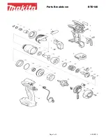
BTD140
Brand: Makita Pages: 3
TD090D
Brand: Makita Pages: 6

DTD148
Brand: Makita Pages: 14

DTD137
Brand: Makita Pages: 84
BTW450
Brand: Makita Pages: 2
BTW253
Brand: Makita Pages: 2
BTW070
Brand: Makita Pages: 6
BTL062
Brand: Makita Pages: 2
BTD136
Brand: Makita Pages: 13

BTD141
Brand: Makita Pages: 28
BTD123F
Brand: Makita Pages: 7
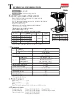
6936FD
Brand: Makita Pages: 8
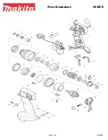
6936FD
Brand: Makita Pages: 2
6908D
Brand: Makita Pages: 4
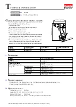
6905H
Brand: Makita Pages: 11
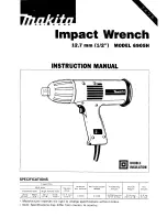
6905H
Brand: Makita Pages: 2


